Not ideal, but it works with some babysitting.
For more AC power than a standard 12V Power Socket inverter could provide, I tapped into the high current DC-DC output from the Tesla PCS (Power Conversion System) under the rear seat.
This is a first trial, not very refined, but functions well with manual Inverter switching assuming it is disconnected from the car during firmware updates.
The Gritty Details
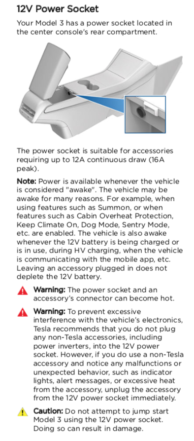
First of all, the only Tesla sanctioned 12V supply that I know of in the car is the 12V Power Socket. As you can see below, it is rated for 12 Amps continuous load. Although a small inverter or my refrigerator can be run from this outlet, it’s not powerful. After losses it will only supply ~110 Watts of 120V AC power.
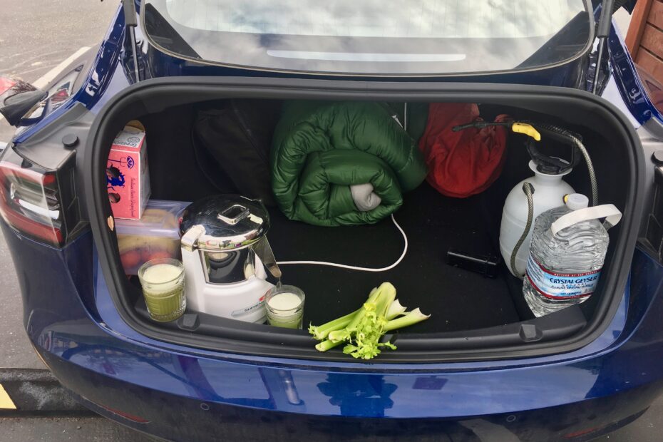
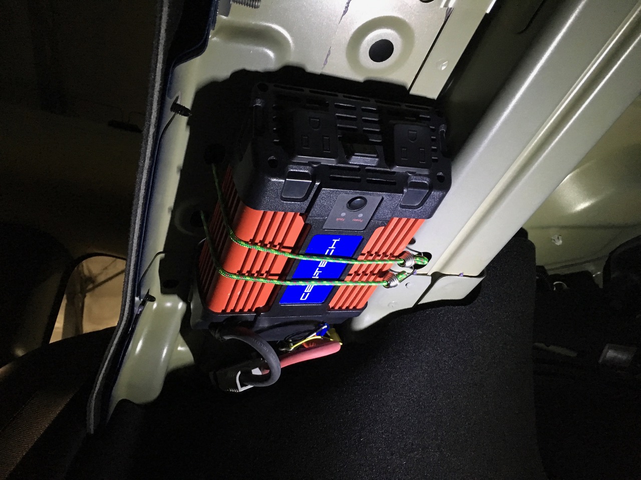
My desire was to run a juicer while camping using a low cost inverter from Harbor Freight. The one I used is rated for 750 Watts continuous, 1500 Watts peak and has been running my juicer and rice cooker for many years on camping trips.
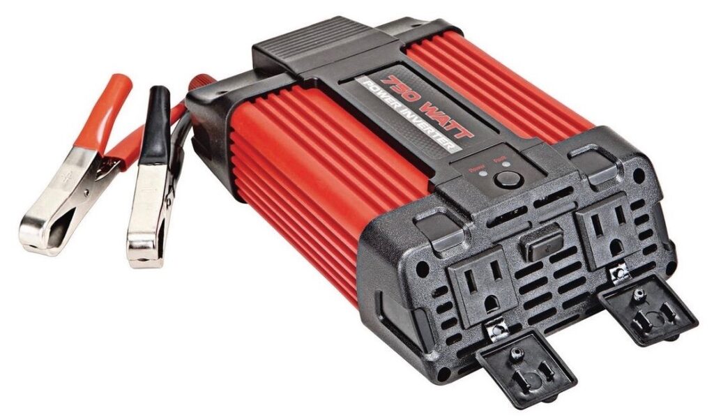
[EDIT, It seems to be discontinued. I have not tested another for the necessary no load when turned off yet. Comment please if you know one.]
https://www.harborfreight.com/automotive/automotive-accessories/inverters/750-watt-continuous-1500-watt-peak-power-inverter-66817.html
Traditionally an inverter like this would be connected directly to the 12V battery on your car, on a Tesla Model 3 it’s not so simple. Due to the battery monitoring device built into the Model 3 VC Front (front vehicle controller) extra loads on the 12V battery will cause the Tesla software to register a fault of the battery. Therefore we need to find another place to tap high current 12V power that won’t upset the Tesla systems.
NOTE: If you have already tripped a persistent fault of your 12V battery that doesn’t clear when the car sleeps, it can be cleared by a full shut down of the 12V and HV batteries (penthouse low voltage connection) for 30 seconds. The sequence is a bit important so it would be advisable to consult the Tesla service manual procedure for that.
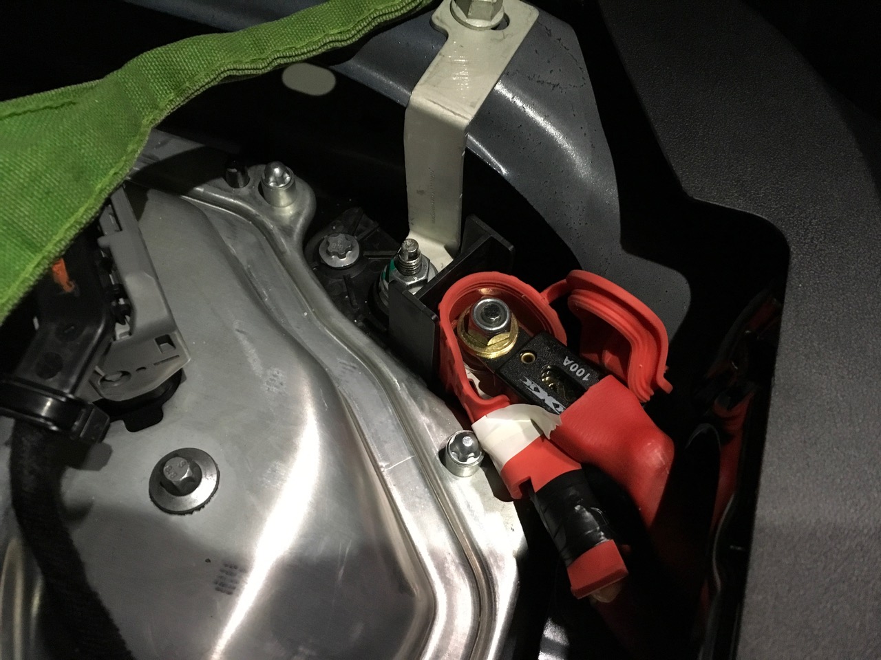
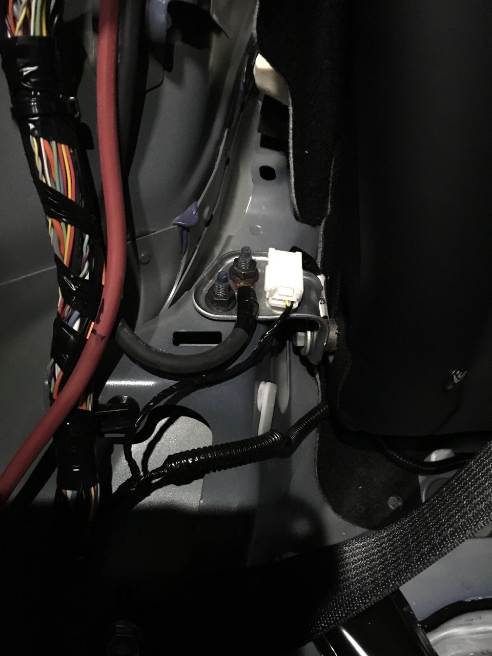
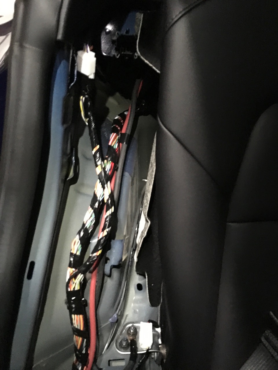
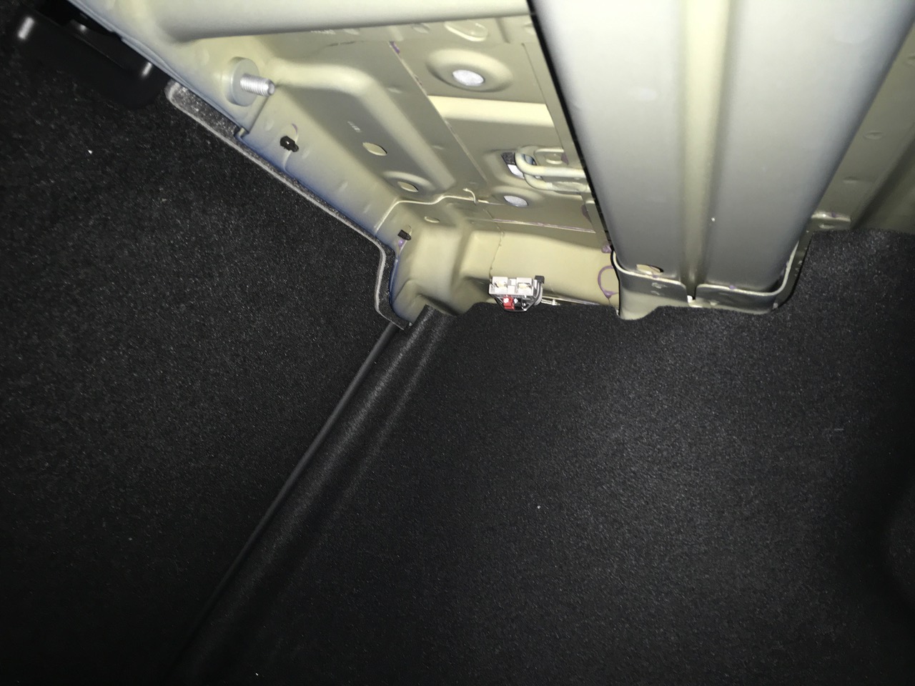
Fortunately there is a high current 12V connection to the DC-DC converter under the rear seat. The VC Front has an e-Fuse that disconnects this terminal from the 12V battery when the car is asleep, but as long as the car is awake the connection provides high power from the high voltage traction pack through the DC-DC converter in a way that does not cause the car to flag a bad battery. This should be safe to use when the car is parked. I would not draw high current when driving since it is important to have enough excess current budget available to run the critical vehicle loads including power steering and brakes.
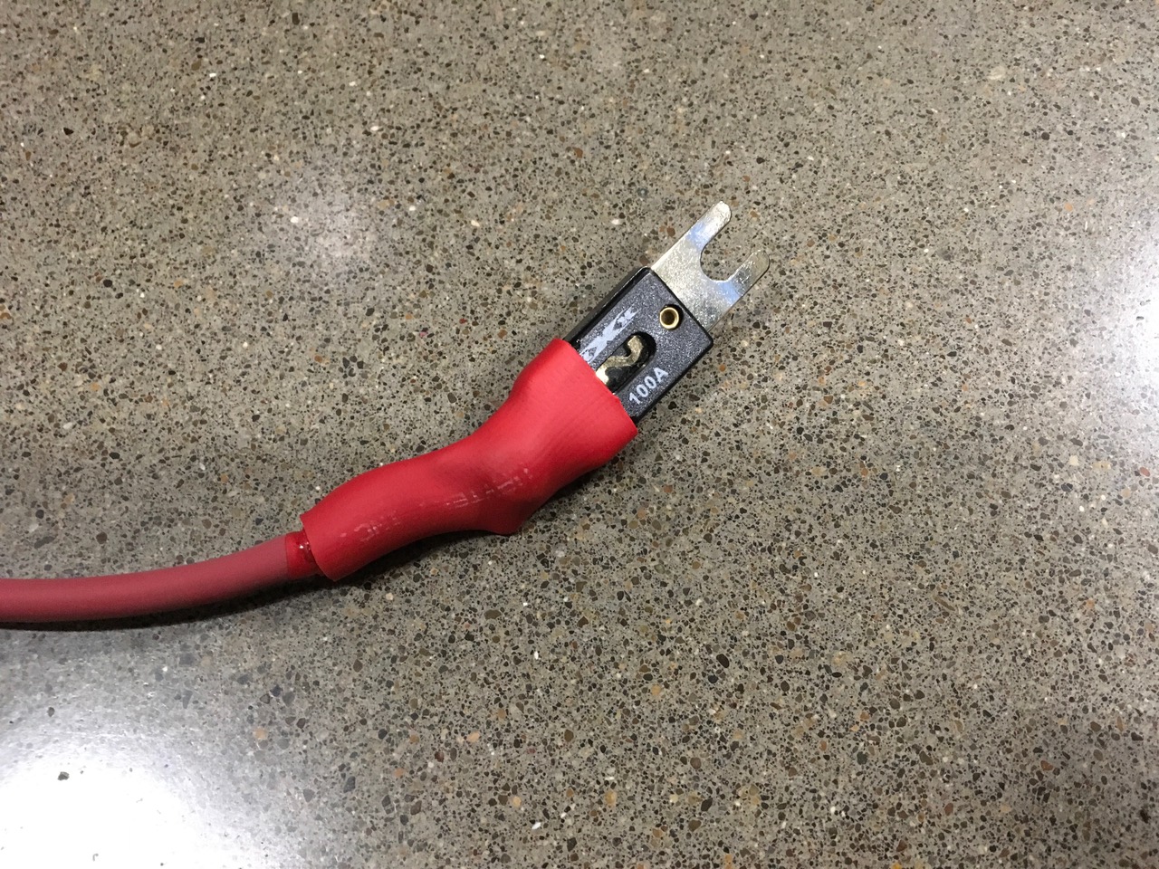
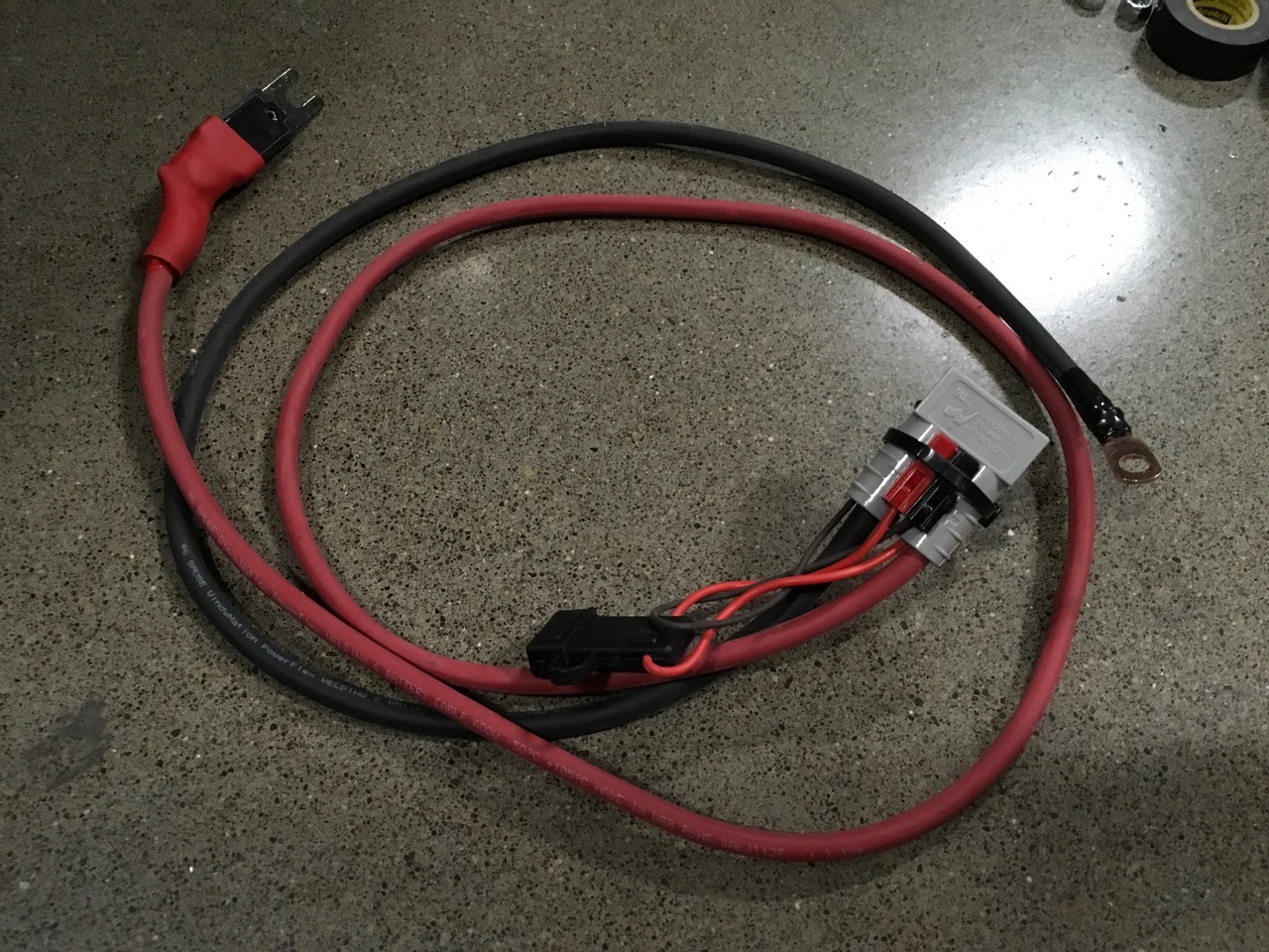
Pictures below show my setup with a 100 Amp fuse and #6 AWG wiring leading to an Anderson SB-50 connector https://amzn.to/2YfpX2P* mounted under the package shelf. Additionally there is a smaller Anderson Powerpole connector with a 15 Amp fuse for plugging in the refrigerator.
This is where it gets complicated.
Although the refrigerator had no trouble running when the car was awake, and worked fine, the AC inverter caused a problem. The AC inverter has relatively large DC filter capacitors connected to the DC input terminals. Rapidly filling these capacitors is what causes the familiar spark when an inverter is connected to a battery. In my experience, approximately half the time that the car woke up, the inrush surge to the inverter would trip the e-Fuse that connected the DC-DC to the vehicle systems resulting in this unwanted fault.
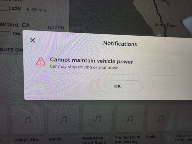
Fortunately, walking away from the car with Sentry, HVAC and Summon Standby Mode switched off and waiting a few minutes (or longer if the 12V battery is charging) will allow the e-Fuse to reset. As far as I can tell, the car just needs to go to sleep to reset it.
Precharge Circuit
In order to avoid tripping the e-Fuse we need a way to gradually fill the capacitors in the inverter and then activate a relay connecting the inverter insuring low inrush current. This is commonly known as a precharge circuit.
I wanted to keep things relatively simple so some compromises were made:
- In order to keep the precharge resistor size manageable, the circuit will not activate the relay if there is any continuous load from the AC inverter while it is precharging. Therefore this circuit only works with some inverters (if the USB outlet in the AC inverter works with the inverter off, then this circuit will probably not work) and the inverter has to be off when precharging or else the inverter low voltage alarm will sound and the power relay will never turn on.
- During Tesla software updates the car cycles the DC-DC power in such a way that conflicts with this system and this can cause the above fault to happen. When this happened to me I was in a hurry so I did a hard power reset of the car (another subject) and all was cleared. A sleep cycle may also clear it, needs verification.
- For the above two reasons, this system works better for occasional use that allows manual switching of the inverter and unplugging during software updates. It would not be helpful for a system that requires the AC inverter to turn on automatically when the car is wakes up.
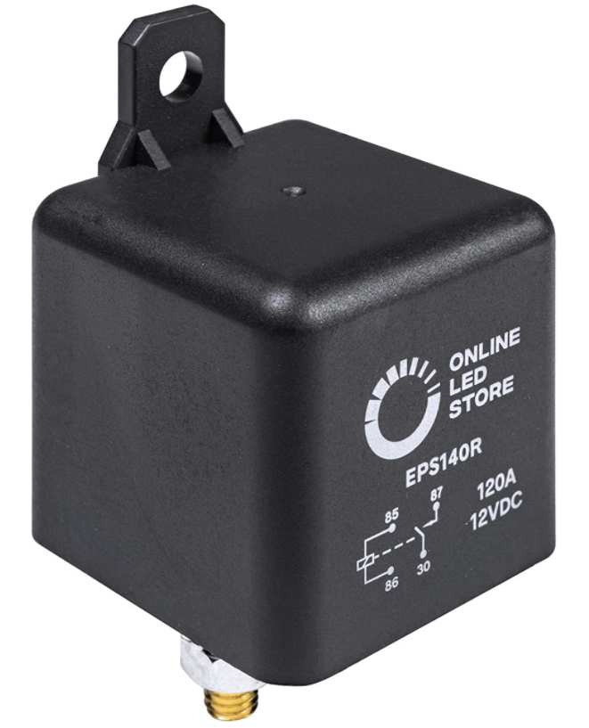
The relay I used came from Amazon here, they also have a 200 AMP option now. *
https://amzn.to/3cIoG9E
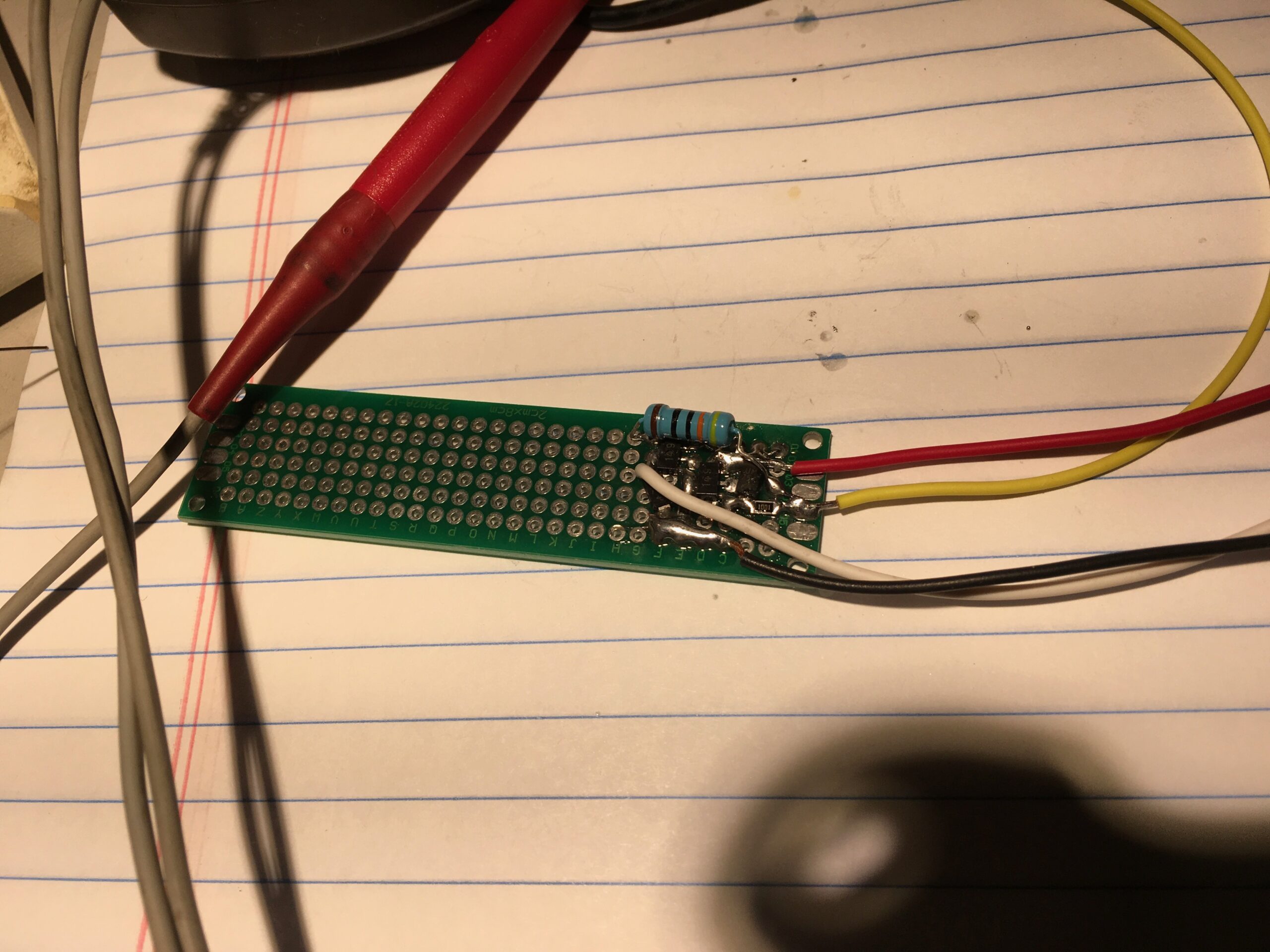
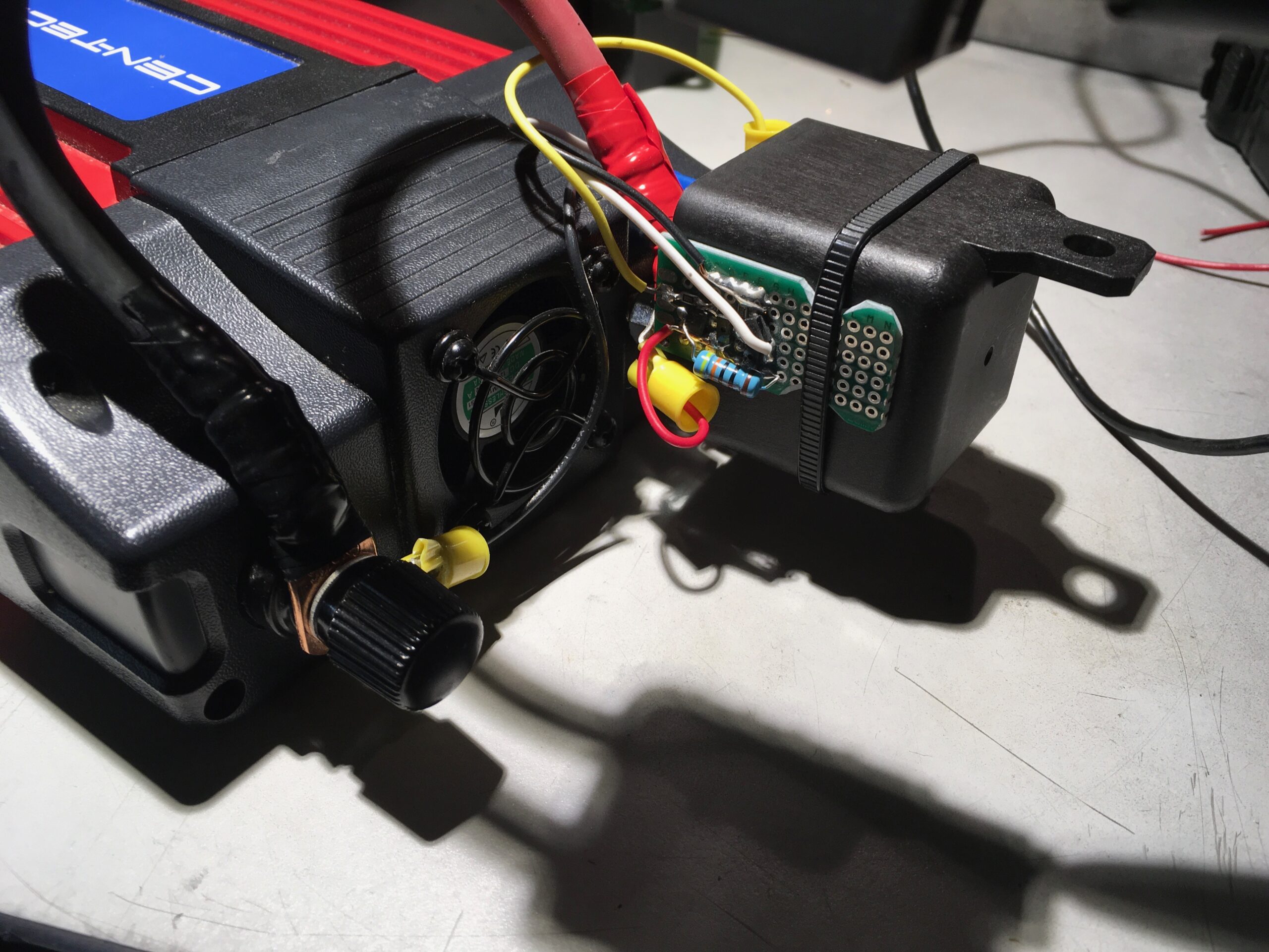
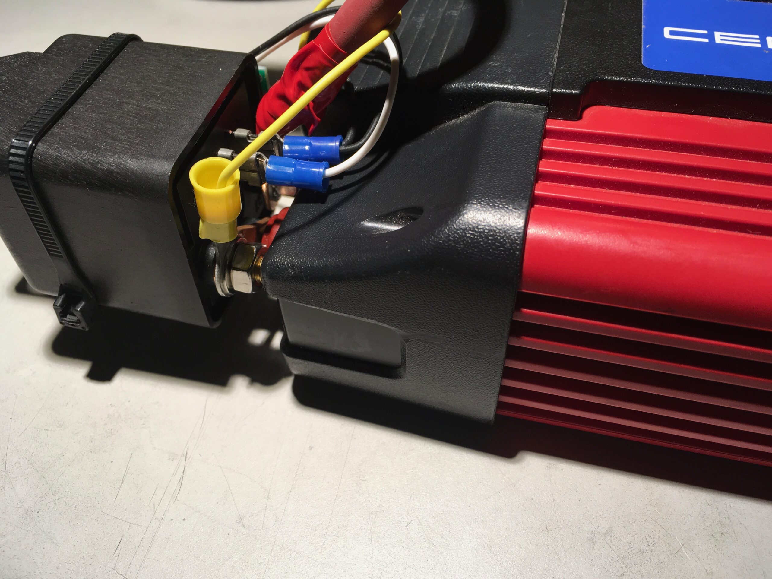
Here is my messy scribbled schematic and pictures of the completed circuit. Click on the images for full size.
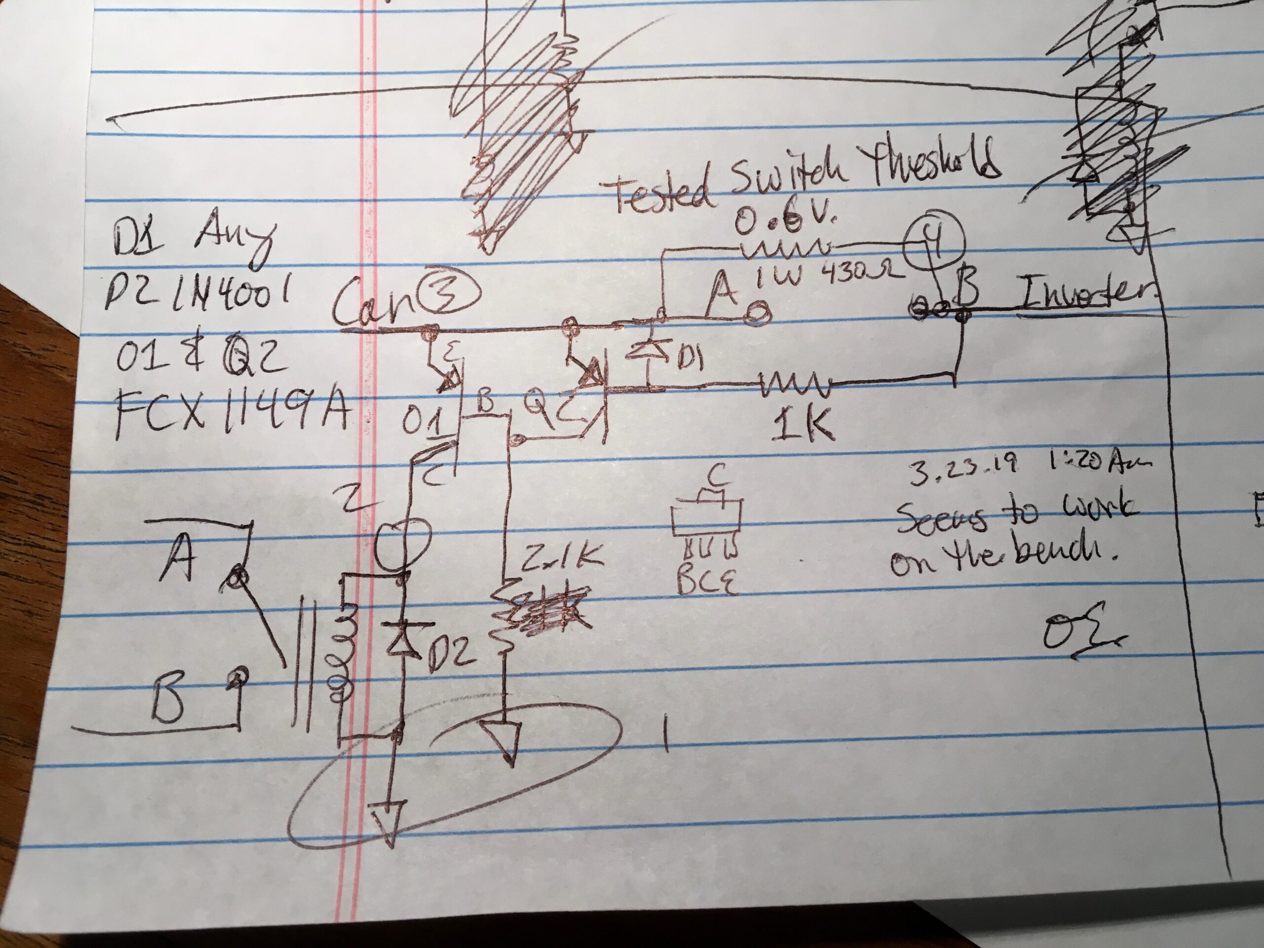
Circuit description:
- The main power relay coil is in the lower left, with power terminals A and B shown and also connected in the upper right as A and B. These connect to the +12V from under the back seat of the car, and the +12V connection on the AC inverter respectively.
- The negative 12V from the car (Chassis ground) and the negative connection on the AC inverter are always connected.
- On the diagram, the number 1 at the two downward pointing symbols indicates chassis ground.
- Number 3 is a connection to the car +12V
- Number 4 connects to the +12V connection on the AC inverter.
- The 430 Ohm 1 Watt rated resistor charges the AC inverter capacitors slowly anytime that the relay is off. It is sized so that it will not overheat even if the AC inverter is left on or incorrectly wired. The other resistors are 1/4 Watt rated.
- Q1 and Q2 are identical PNP transistors. I happened to have FCX1149A’s around since they are used in Zilla controllers, but many PNP transistors would work. The E B C on Q1 and the top package view indicate Emitter, Base and Collector.
- The 1K resistor to Terminal B turns on Q2 anytime B is 0.6V or more lower than A by pulling current through the emitter and base of Q2. This pulls the collector of Q2 up to A, which holds Q1 off.
- When the precharge resistor charging the inverter capacitors causes the voltage difference from A to B to drop to 0.6V, Q2 turns off, which allows the 2.1K Ohm resistor to turn on Q1 by drawing current down through the emitter and base. This causes the collector of Q1 to pull up to the car +12V at 3, providing +12V to turn on the relay at terminal 2.
- If there is a load on the output B, such as an AC inverter mis-wired or left switched on, then the precharge resistor will not be able to reduce the A to B voltage and so the relay will remain off.
- Once the relay has turned on, the AC inverter can be switched on and loaded.
- When the car goes to sleep and the +12V power from the car drops below the relay coil required hold voltage, the relay turns off.
- Diodes D2 and D1 protect Q1 and Q2 respectively from reverse voltage spikes when the relay turns off. Any diode rated for 1 Amp and 50V or higher is more than enough.
Future Plans
Originally I thought it may be worth drawing up a PCB to make these easily. But with the following sub-optimal issues, I’m not convinced it’s worth it for the few of us that may want one. Feel free to tell me what you think below. (Hopefully it will notify me, if I’m missing, find me on twitter at https://twitter.com/CafeElectric)
- 1) It would be nice if it didn’t fault the car when left connected during software updates. I have not studied this enough to know what causes the issue. A voltage trace of the DC-DC power during update would probably reveal much.
- 2) The need for the AC inverter to be off when precharging is limiting. A lower precharge resistor with higher power could overcome this issue, but by the time you have that size of resistor, say 2 ohms to allow startup into a 1A load, then the fault situation is about 7 Amps and 100W, which requires a very large power resistor and an even larger heatsink to keep it from blowing up. Combined they may be larger than the AC inverter. Alternately a properly sized PTC self resetting fuse may work well, as I did with Zilla controllers, but that requires much more engineering. Still, it would never be able to start up if the AC inverter had a load plugged in and turned on. I have seen some people use a low value resistor with only a relay driven off the load side, and although you can get away with that, I am not comfortable with the fault conditions.
Some AC inverters may have a control input that could be switched on after the power relay has completed its turn on. Adding that to my AC inverter was going to get messy so I did not pursue it, but that may be worthwhile to some even if it requires more circuitry to drive it. In that case, a load could be left connected to the inverter and it all would function automatically.
*This site contains paid links, by buying through these links I may receive a commission for the sale. This has no effect on the price for you.12
This is a blog only of my musings and experience.
THE INFORMATION IS PROVIDED “AS IS”, WITHOUT WARRANTY OF ANY KIND, EXPRESS OR IMPLIED, INCLUDING BUT NOT LIMITED TO THE WARRANTIES OF MERCHANTABILITY, FITNESS FOR A PARTICULAR PURPOSE AND NONINFRINGEMENT. IN NO EVENT SHALL THE AUTHORS OR COPYRIGHT HOLDERS BE LIABLE FOR ANY CLAIM, DAMAGES OR OTHER LIABILITY, WHETHER IN AN ACTION OF CONTRACT, TORT OR OTHERWISE, ARISING FROM, OUT OF OR IN CONNECTION WITH THE INFORMATION.
Thanks for posting this, Otmar!
Do you know how much power the DC-DC will put out? Of course it is shared with the other car 12V loads, but I’m just wondering how large of an inverter it would support?
cheers,
Andrew
I forget if it’s 200 or 250 Amps. IIRC it’s 2500 W so that’s closer to 200A.
Last year, I rigged my Model 3 to supply ~1kw 12dc to some grid-tie inverters in order to supplement my PowerWall. Some discussion here:
https://teslamotorsclub.com/tmc/threads/powerwall-2-0-backup-runtime-extender.126358/
Also, one of my blog posts on the project:
http://wmckemie.blogspot.com/2019/09/micro-grid-and-augmentation.html
Photos including Model 3 12v connections:
https://photos.app.goo.gl/1zCvjxzJXnwHjHu98
I don’t much use the 12v PW augmentation because the available 12v grid tie inverters are not very efficient. PV panel micro inverters driven by 36v golf cart batteries are much more satisfactory.
Interesting mods there.
Enphase has been upgrading the early less reliable microinverters (190W?) and the old ones are going to local electronics recycling. I’ve grabbed 50 or so just in case a use could be found. They are internally potted so very difficult to modify. Yours is the first use I’ve seen that might fit. 🙂
Very nice writeup and thank you for this info Otmar!
Although significantly more expensive, and ‘takes up ore space’, there is one ‘warranty friendly’ way to do all of this. Get one of the Goal Zero Yeti portable “lithium generators” such as the 500X model. They have an option to charge from your 12V lighter socket (at a steady 100W or similar) and they have plenty of capacity and power output to handle both the surge and continuous power output of devices like the mini fridge.
The downside of course is the Yeti will only charge when the car is on (12V lighter socket) and there’s still some chance you could run out of power.. But 1 hour of charging from the car (~ 120W) sounds like it’ll handle 10 hours of Fridge discharge..
This setup would also reduce any warranty claim risks with Tesla or chance of the ‘can’t maintain vehicle power’ error during updates or elsewhere.. Technically they can also be charged via solar panels, so you might be able to rig up some panels attached to the back glass or similar for charging at all times..
Could you put in a large capacitor (such as used for large audio systems etc) before the inverter, and put the pre charge circuitry on it, so that when the inverter turns on the capacitor charging spike is supplied by the size matched external capacitor?
You would then leave the inverter always switched on, and control the system with a seperate switch that would control the 12v relay and precharge system, so turning the switch off would drop the relay out removing power from the inverter, and turning the switch on would enable the precharge system, which would pull the relay in when the external capacitor was charged fully.
The other idea would be to see if the internal capacitors are at 12 volts, and if so, seperate them from the inverter control system so that you can precharge them and not activate the inverter until they were ready.
Basically put a relay between them and the inverter.
If they have complex circuitry themselves this may not work, but if they are just wired in parallel across the 12v buss it might be easy.
Yes, very large caps could work. You are thinking creatively!
They are large and expensive and the system just got more complex with dual switched power paths.
Disconnecting the caps in the inverter is not practical since inductance paths must be short, but the power section and caps are not causing the constant draw issue. So if you are willing to open up the inverter, then you may as well change main control switch to turn off all the control electronic loads like it does in the inverter that I used.
If you are willing to open the inverter and rewire the control electronics switch, then you could also control that switch with another output from the precharge circuit, making it all automatic turning on and off.
I was just trying to keep things as simple to implement as I could. Engineering is always a tradeoff between complexity, cost and performance.
Good points.
And on a harbor freight inverter, I have no problem hacking it, worst case scenario I have to spend another $40 bucks lol
Yes, I also love the joys of hacking cheap things.
They just discontinued this red inverter a few days ago. The new one is black and I have not looked at one yet.
In theory, hang with me for a second, then rate my dumbness on a 1-10 scale…
Could you not just connect inverter input also to a 12v battery in parallel to maintain a precharged state on the inverter?
So when the car is off, the DC filter caps in the inverter are topped off by the 12v battery, so we don’t get that alarm d/t the inrush surge at cold start when the DC system kicks on.
Use a spare 12v, not the onboard, because we don’t have to be nice or very concerned about it’s longevity. Hang a battery maintainer off the inverter to trickle charge it anytime the car is running, such that it stays not entirely dead. Do we need more?
Not classy, but if it works, is it really stupid? Not saying it does work, asking moreso.
I guess the real question is how much do the capacitors need to avoid the inrush surge, and how cheap of a battery can provide that yet would function long enough in this arrangement?
Creative ideas are a great thing!
What you describe sounds possible to me. That said, I think you would need to disconnect your extra battery and inverter from the DC-DC power when the car is off. It seems to me you would then still need a relay and some control circuit which may be more complex in the end.
Otmar,
What if I wanted to charge my camper’s 12V 200 Ah LiFePO4 battery using the DC-DC output from the Tesla PCS? I have an old 30A PWM solar charge controller at the moment doing the battery charging duty with a Uni-Solar PVL-144 solar panel. The Tesla would, in effect, replace the solar, or perhaps, add to it.
I think I would have to use a boost converter to step up the voltage from the Tesla, correct? Or, perhaps, use a proper LiFePO4 battery charger. What do you think?
-Bob K.
I can see how that would be very tempting, but offhand, I don’t know of a way to do that safely and automatically. If I knew more about the internal systems of the DC-DC type lithium chargers I might have some ideas, but I’m not familiar with them.
Besides the issue I describe above concerning only drawing power when the car is awake, you would also have to be careful to not draw too much when driving or it may compromise the vehicle power steering and braking supply needs. You may get away with some sort of manual control when parked, while also watching out for inrush loads, and you might need a charge controller that you could turn off while connected so it doesn’t draw current while precharging the PCS connection. It’s really going to depend a lot on the charge controller internal design.
It seems to me you could use a DC to DC style charger that’s limited to 10 Amps input on the cigarette lighter connection with little risk even while driving.
What is the ring nut size that connects to the 12v penthouse output? I see links for the Anderson connector, relay, but disappointingly not the 100A fuse used that would have allowed me to answer this question myself 😉 And, no, my car is not in my possession currently to check, but need order a ring nut for s similar project before it is again 🙁
Ah, the perils of using parts that I had lying around!
I’m 95% sure that the stud is 8mm, so. 5/16” terminal should fit.
I also am not near the vehicle at the moment.
Have you checked out using an NTC Thermistor as an inrush current limiter?
https://en.wikipedia.org/wiki/Inrush_current_limiter
https://www.ei-sensor.com/thermistors/inrush-current-limiting-power-thermistors/
https://www.digikey.com/en/products/filter/inrush-current-limiters-icl/151
Hmm, answering my own question, one that handles 80 amps is $34 and is probably pretty large and gets pretty hot, so perhaps not ideal:
https://www.digikey.com/en/products/detail/ametherm/MM35-0R280/7652440
Finding an inverter which has much less input capacitance might be easier.
Otmar, I have moved away from the DIY battery for my camper. I have replaced that with an Ecoflow Delta Pro Portable Power Station (https://ecoflow.com/products/ecoflow-delta-pro-portable-power-station). It ticked all the boxes for my needs, most significantly its 120V/30A TT-30 outlet. Now, to charge it from the Model 3…
The Delta Pro can be charged via its DC input port, limited to 15A, 11 – 150V, 1600W, mostly meaning solar (or perhaps, wind at some future point).
It can also charge from an automotive 12V power port and comes with a cable for that, limited to 8A. I’ve tested that connection. 14.5V from the Tesla power port, and the Delta Pro shows 110W input, which equals 7.6A (110W/14.5V = 7.58A). Well below the 12A limit of the Tesla power port.
The question is this: if I wanted more wattage from the Tesla (I had a 12V power port installed in the trunk, connected to the PCS), I could use an adjustable voltage booster (the one I purchased is limited to 15A input/output) to pump up the voltage to, say, 48V to take advantage of the Delta Pro’s DC voltage input range.
Thus, if we pull 15A from the Tesla @ 14.5V, that’s 217.5W, feed that through the voltage booster set to 48V, 4.5A will be pushed to the Delta Pro, or 217.5W.
Is my math correct? Is there a way to get more power for this project?
It looks like your reasoning is sound.
I’d be concerned about too much power from the PCS when driving, but while parked I expect it should be fine.
In order to get more power you would need a boost converter like you have, but with a higher input current rating. While parked it should be no trouble to pull 100A from the PCS.
Alternatively maybe you could use several of your 15A converters in parallel.
What hurdles would you expect if you connected a huge three phase inverter directly to the high voltage junction box? lets say like a growatt three phase 20kw inverter directly hooked up to the 400v system for off-grid use/ v2g. is there monitoring of the battery voltage throughout that would hinder this setup to be used while stationery?
Aside from the lack of high voltage junction box (it’s all inside the penthouse of the battery) I don’t know the system well enough to know if it would tolerate a high voltage direct load. It might throw a fault or blow the pyro fuse in response to unexpected loads, I just don’t know.
Thanks, Otmar! I’ll test a couple of 12V boost converters to see what output I get and if the car complains. I purchased 2: a 12V – 24V 20A (360W) and a 12V – 48V 20A (720W). I expect to draw 26.6A and 53.3A, respectively from the PCS, if my math is correct.
6AWG cable, 100A fuse, from the PCS to a heavy duty switch to a 75A Anderson panel mount connector; I then will have the option of plugging in nearly anything I want. Sort of a universal PTO.
I figure the car charging cable (12V/8A max) shouldn’t be an issue while driving. In fact, I just did an overnight test on it with Camp Mode enabled. The car allowed it, 10 hrs worth @ 100W, I was able to open/close doors and trunk, finally closing the trunk at bedtime. Of course, Sentry Mode was disabled. Checked on it first thing in the morning, still going. It’s pedestrian, at best, but it works.
Since I’m skipping the inverter step, is there any reason to consider an inrush of current to my Delta Pro when I plug in?
Hi Otmar!
This post may sound off-topic, but it is EV conversions related.
I’ve been converting cars in Mexico for the past 10 years using mainly DC Series Motors, some AC Motors, PM, Hub toys. In the road I have destroyed a couple DC Motors for the 2 vulnerabilities they have: OverRev and OverHeat, especially if you use them with High Voltage or High Amperage. Now I have both variables under control in the dash so that every implementation takes proper actions to avoid disasters. I also implemented a Cruise Control circuit, which is Controller-independent, similar to your early Regen Circuit on the Old Curtis Controller.
Dear Otmar as the father of Racing Controllers in the world, a living legend, I wonder what happened with your twin 8″ ADC Motors in your car? Why did you abandon that Motor-Controller option in your projects? Your Zilla Heritage is still the most powerful controller for DC Series Motors. The answer is almost at sight: maintenance-free, regen, eficiency, but what about cost and simplicity?
I have 200 Mile range in my EV conversion using one ADC 9″ motor at 144V, 400Amp controller, Samsun 21700 cells. Racing is not a priority for me, range is. Having long life on components is also top priority.
Best regards and full appreciation of your contribution to the EV History.
P.S. I also plan to hack Tesla and put those Motors in vehicles… some day.
Hello Hector,
It sure sounds like you are doing wonderful things, and it’s great to hear that you implemented automatic overheat protections for the motor. Brush overheat protection is something I always wanted to do, but I never finished a brush temperature sensor nor the integration of it.
My old twin 8″ motor setup with adaptor plate is sitting under my bench, want to buy it? 🙂 The motors were having problems. After I turned the commutators and rebuilt the brushes I discovered that the armatures had probably overheated and the electrical leakage damaged the motor and transmission bearings. I should have had overheat protection, or a extra fan on them. I still remember the long drive that probably killed them. Eventually I sold the car without the dual motors, including a single DC motor and transaxle setup for the new owner to use.
When it comes to economical costs for low volume conversions I think it’s hard to compete with the cost of used OEM parts like those from the Leaf and Tesla. The people on the forum at https://openinverter.org/ have done a great job making AC performance with used parts economical. It is a lot of work to learn the details, but the results seem worth it.
As you say, efficiency, cost and simplicity are all good values. Regen has not proven to be maintenance free with available DC motors, AC is much better for that. My belief is that low volume DC production is too expensive to compete with used parts from high volume AC cars. I wish I were wrong, but that’s why I stopped trying to develop DC systems. I kept the price of the DC systems artificially low by paying myself very little, but now we have OEM AC units and I don’t see a value in making new DC products in low production volumes.
I wish you success on all your projects!
Comments are closed.