If you are repairing a bricked Smart ForTwo ED3 Electric Vehicle, this may be useful.
I’m in the midst of replacing a dead cell in the traction battery pack on a 2014 Smart ForTwo ED3 electric car.
The forums at smartcar of AMERICA have been super helpful, and yet I was struggling to easily test my current sensor. Here I offer a simple bench method as well as an Arduino based setup for testing the sensor yourself.
As far as I know, the Bosch EDS2 sensor part number 0442B0301E in the Smart ED3 is not available as a replacement part. There is someone in the Ukraine who has found a way to modify a different sensor to work, presumably by transferring the ED3 firmware. This is wonderful, but at the current price of $650 including shipping on eBay I wanted to be able to test sensors first to see if I need one.
The sensor communicates using LIN bus. I’m no expert at LIN bus, and when I looked for a simple low cost LIN scanner I came up short. So I’ve decided to assemble one myself and offer up instructions here on how you can use it. This scanner can be used to test for response for other LIN devices with minor code modifications.
Simple Hardware Bench Test:
But first, there is a simple test that can tell if the EBS2 sensor is totally blown. A common failure mode involves the sensor electronics being blown by excessive high voltage on the 12V power supply pin. If you have a 12V supply and meter that can read milliamps of current, you can check if the current draw is reasonable.
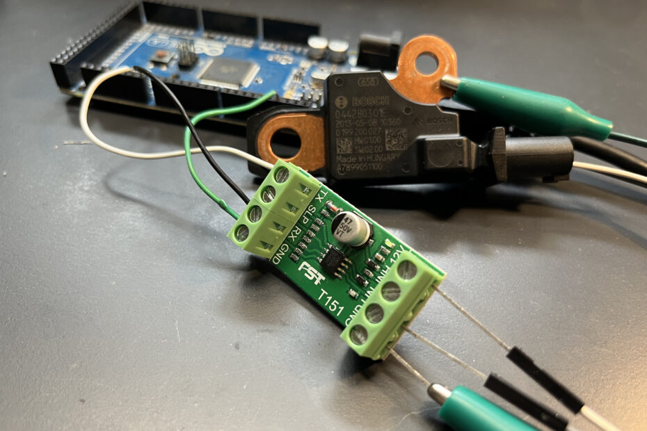
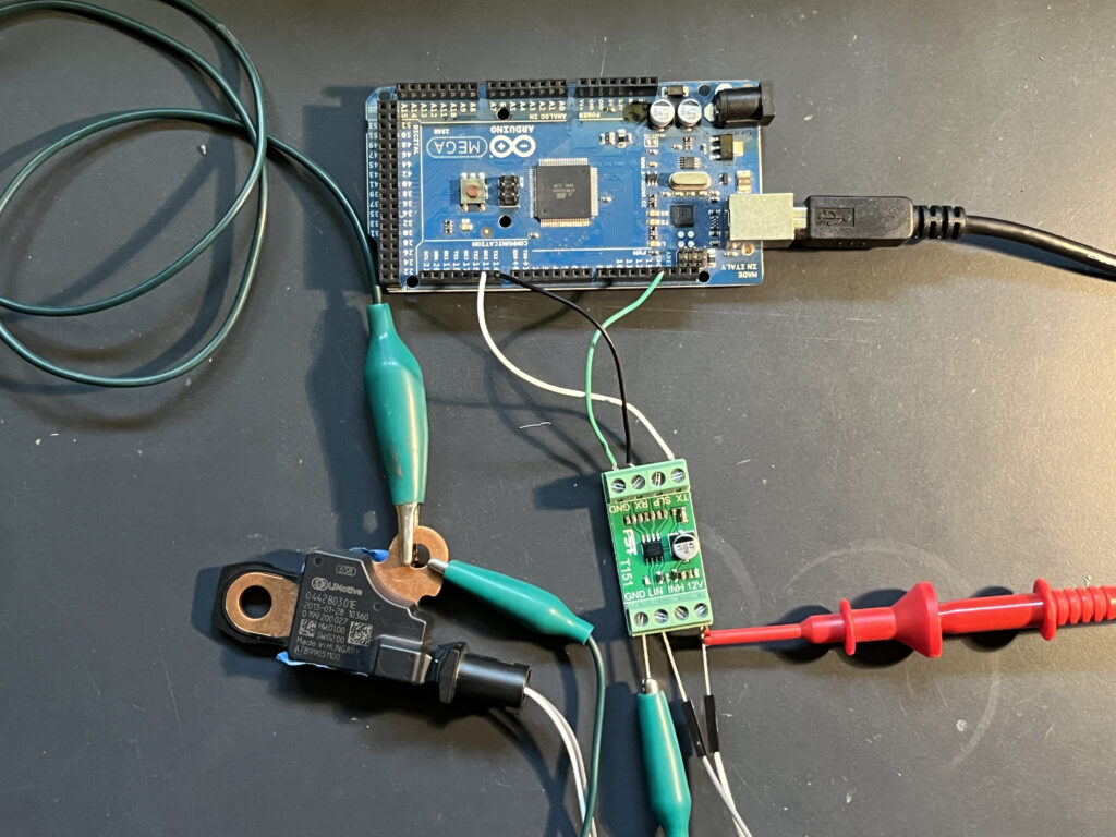
The sensor has a copper bar with two bolt holes, that is the negative connection. It also has two pins inside the connector. With the sensor sitting flat with the printing visible, the upper pin is for +12V (white wire in picture) and the lower pin is the LIN connection (grey wire in picture). Thanks to Jmk2020 for this info!
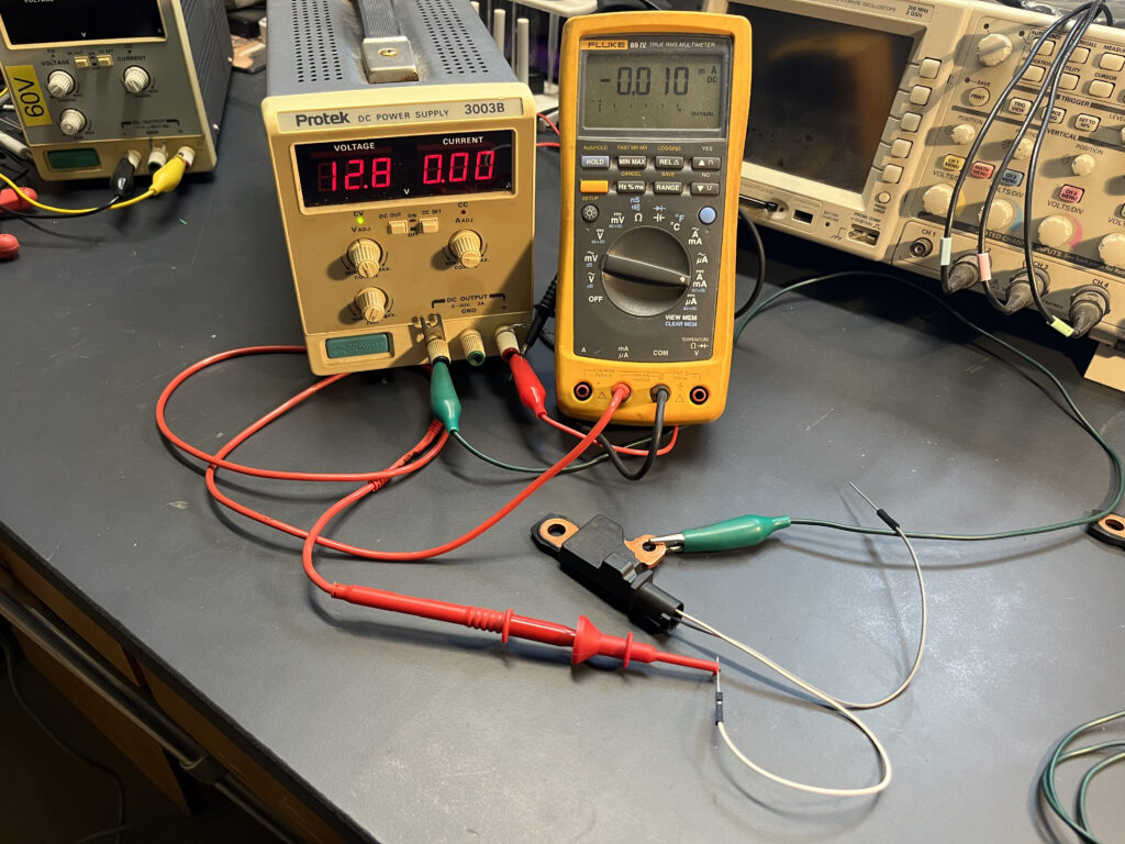
First, connect the 12V supply and check that the current draw is very low. Mine would vary between 10 uA when warm and 93 uA when cold. That’s as low as 0.010 milliamps and may be difficult to see on many meters. If so, just move on to the next test.
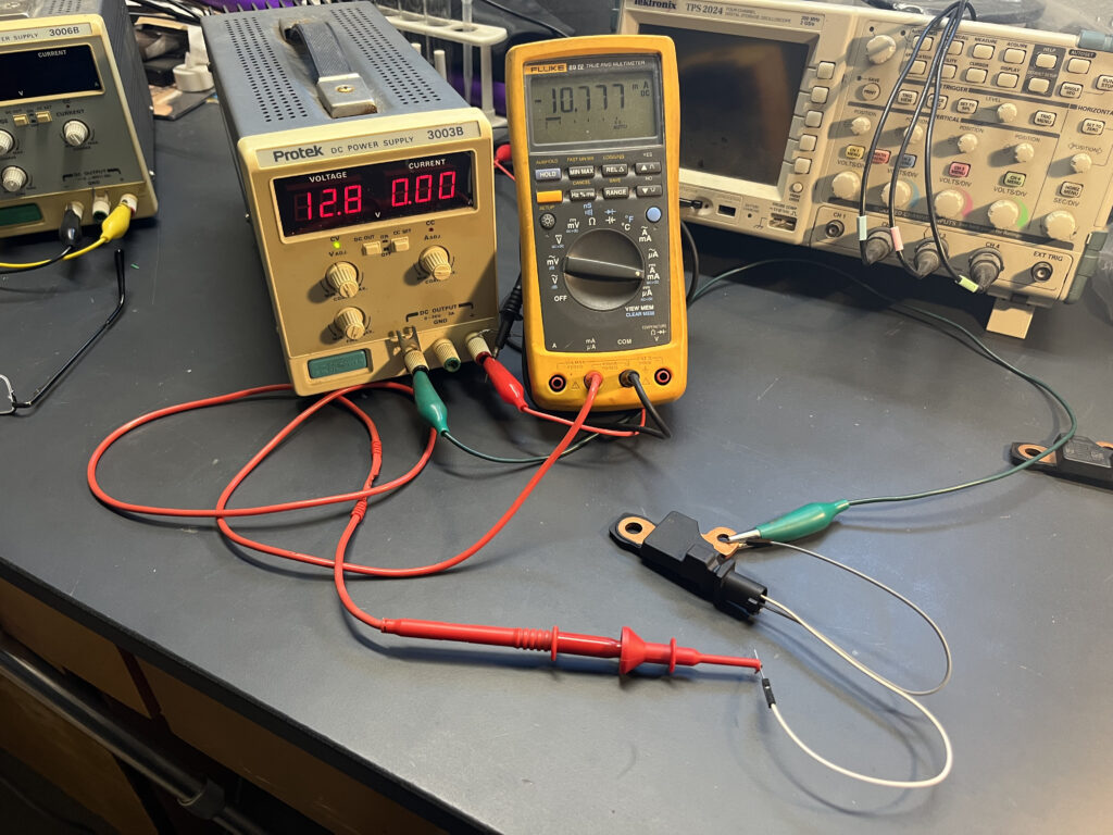
Next, tie the LIN connection to ground to send it a Sync Break signal and you should see the current go up to somewhere between 1 and 15 milliamps. When you disconnect the LIN to ground connection, the current should drop back down after a delay of about 3 seconds. I find that the same sensor sometimes only draws 1 mA, and other times draws 10 mA. I don’t know why it does this, but I suspect some internal system might be using the current to warm up an internal circuit to maintain accurate readings. After storing a sensor in the freezer, I found it drew 10mA for a long time.
If the above tests are good, then you are starting to get lucky! I’ve heard of one that drew 100 mA and I suspect that would be a sign of a bad sensor, as would be one that does not respond to grounding of the LIN signal.
LIN Communication Testing:
Next we can check that the sensor responds to LIN requests.
I am going to assume that you are familiar with loading Arduino sketches in general. If not, I’m sure there are many online resources to help.
For this you will need some equipment. In addition to a capable of supplying 12V, you’ll need some wires and the items below. If you are on a strict budget, ebay and Alibaba may have discount knock offs. I do like to support the Arduino official store when possible as they have empowered so many.
Arduino MEGA R3 Board ATmega 2560
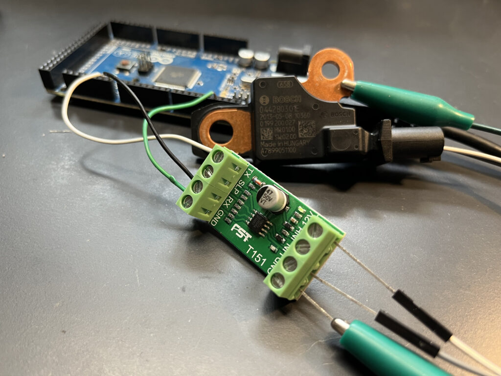
T151 Bus Module Transceiver,LIN Data Analysis Board LIN Converter Data Analyzer
Jumper Wires Assorted Kit Male to Female Multicolored Ribbon Cables These are handy for fitting on the EBS2 pins.
Alternatively the Arduino UNO can be used instead of the MEGA 2560 with different code
A low cost current limited bench power supply
I’ve written an Arduino sketch to do the scanning by modifying some library examples. My code and the library are both free to use open source with MIT license.
If you have the Arduino MEGA 2560 you’ll want to download LIN_PID_Scan below which contains the main file LIN_PID_Scan.ino
If you have a Arduino UNO you’ll want to download LIN_PID_Scan_SoftSerial_231015 below and read the notes in the main file LIN_PID_Scan_SoftSerial.ino since it differs slightly from the comments in the video below as this version was an afterthought.
Once you have the zip file with code, unpack it and put the whole folder titled “LIN_PID_Scan” or “LIN_PID_Scan_SoftSerial” in your Arduino sketch folder. Then open the .ino file and read the notes at the top.
In those notes you will find instructions for connecting the T151 to the Arduino board as shown in the pictures here.
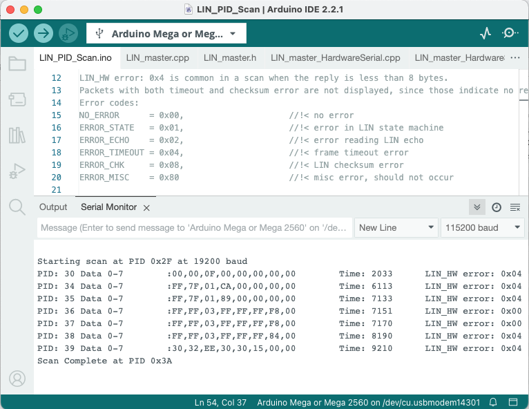
Above is the Arduino result of a test of a good working sensor using the MEGA 2560.
For additional guidance, I’ve made a short video showing how it should work and some possible diagnostics.
By the way, you can restart the scan by pressing the reset button on the Arduino, there is no need to unplug the USB cable or reload code like I was doing in the video.
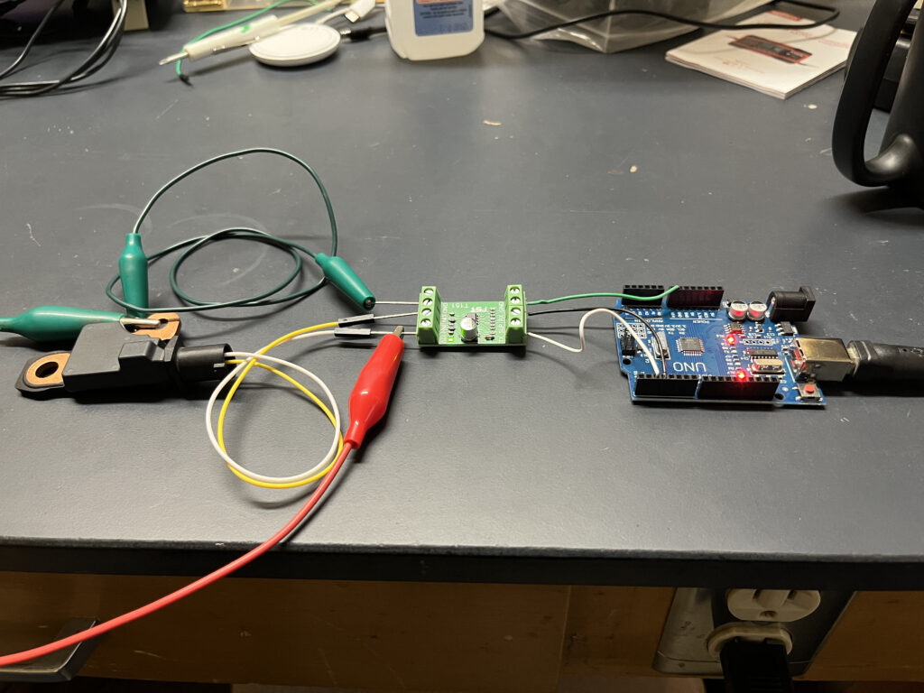
As an addendum, the above picture shows the wiring of the T151 with a Arduino UNO. The UNO version does not fail in the same way as the MEGA 2560 to incorrect or missing wiring, but it still works well to indicate a good current sensor.
I hope this is helpful!
Please let me know if this helps you (I’m curious how many of us are struggling with this) and also if you find mistakes that I should fix. I’m sure I made some!
-Otmar
This site contains paid links, by buying through these links I may receive a commission for the sale. This has no effect on the price for you.
Thank You. I’m going test my sensor soon by this way. Are you working with smart HV battery 451? I have smart 2013 and I’m trying fix it. John Cy
Yes, I am working on my 2014 Smart ED3 battery. I believe that is a 451, but so it the ED2. I have 2 good sensors, and some used replacement cells. I’ve been busy with other projects but soon hope to get back to it. I need to replace one cell, reassemble the pack and clear codes to get it running again.