Key Points before I get into it:
- This post includes instructions to hack a low cost (<$10) Sonoff S31 device enabling the S31 to turn off battery chargers before the battery reaches full charge.
- USB powered devices are simpler to charge limit using a Chargie. Some devices, like Tesla EVs, some phones and other devices have charge limiting built in.
- If your device uses a LFP (lithium iron phosphate) battery, then full charge has much less detrimental effect on lifetime and so this may not be needed.
- The S31 mod requires potential soldering and some code loading. It may be an adventure for a beginner in electronics.
- Once the S31 is programmed, it works stand-alone with no WiFi connection needed. The button on the side turns it on and the programmed script will turn it off again.
- In addition to a computer, you will need a Sonoff S31, not the Lite version, and a 3.3V USB to TTL serial converter as well as some way to connect the serial converter to the board like wires and solder. I used an obsolete LilyPad FTDI TTL converter since I had one, a newer versions seems to be the Beefy 3. I hear that unlike some converters the DSD TECH SH-U09C2 also works well.
- Although the modification and programming process is a bit tedious, I get great satisfaction from the empowerment of being able to overcome the planned obsolescence of the batteries things that I own.
Why:
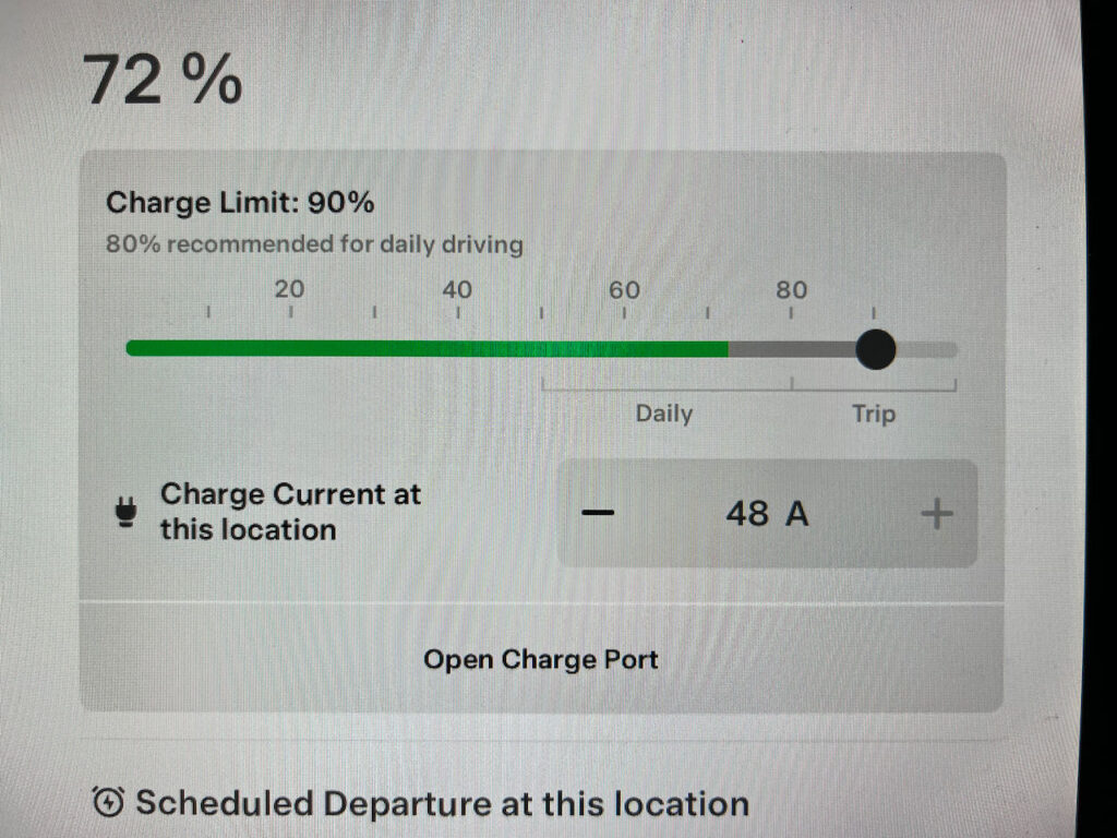
Lithium batteries have shorter lifetimes when stored hot and at high state of charge. I like to optimize the life of batteries in my computers, phones, power tools and other devices by limiting the how fully they are charged most of the time since I rarely need full capacity. Tesla is known for making lithium batteries last a very long time. You can see below that the car allows setting the charge limit, and that 80% is the suggested maximum unless needed for longer trips.
Unfortunately, most devices don’t give an option for limiting charge level, and fully charged batteries are slowly destroying themselves much faster than necessary. Sometimes it’s possible to unplug a device charger before the battery is fully charged and it would be nice to automate that. That’s what we are accomplishing here.
For my cell phone and many USB charged devices, the Chargie is an option I use. From Chargie: “The Chargie app normally runs on your smartphone, but now you can limit the charging of any kind of lithium ion battery, or of a phone that’s been shut off. It will cut power at about 90%, based on power measurements done automatically and continually by Chargie’s hardware.”
That still leaves a lot of devices that are not USB powered. Electric bikes, laptops, power tools and even the ride on mower all charge on a 120V plug. I have not seen a commercial device for controlling those.
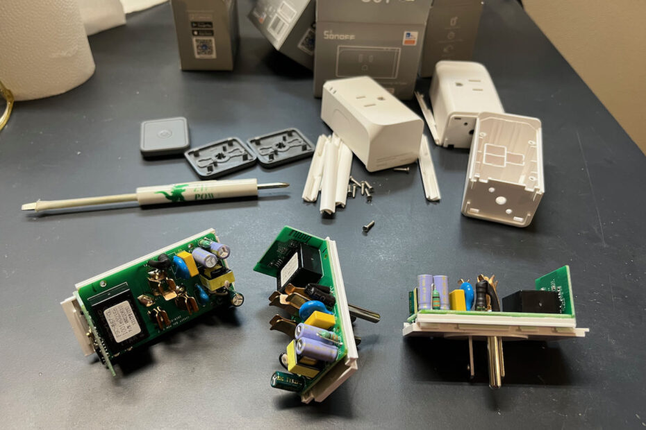
Recently, my good friend Hai-Yue Han shared that he was modifying the Sonoff S31 to do charge limiting. Fortunately for us all he has already done the work of compiling a special version of the Tasmota firmware that can handle the scripts. This allows us to write custom scripts tailored to individual devices that turn off the chargers before the battery is full.

The Sonoff S31 is a wonderful Wifi Smart Socket that can monitor power consumption. It comes with factory firmware that I found unusable. Fortunately Tasmota offers open source firmware for ESP devices and has a console that allows loading custom code called Rules to control the output using various parameters.
A quick test with a Kill-A-Watt (The Sonoff doesn’t measure low enough values) indicates that the Sonoff draws 0.7W to 0.9W when the relay is on, and less than 0.5W when the relay is off with much variability in time.
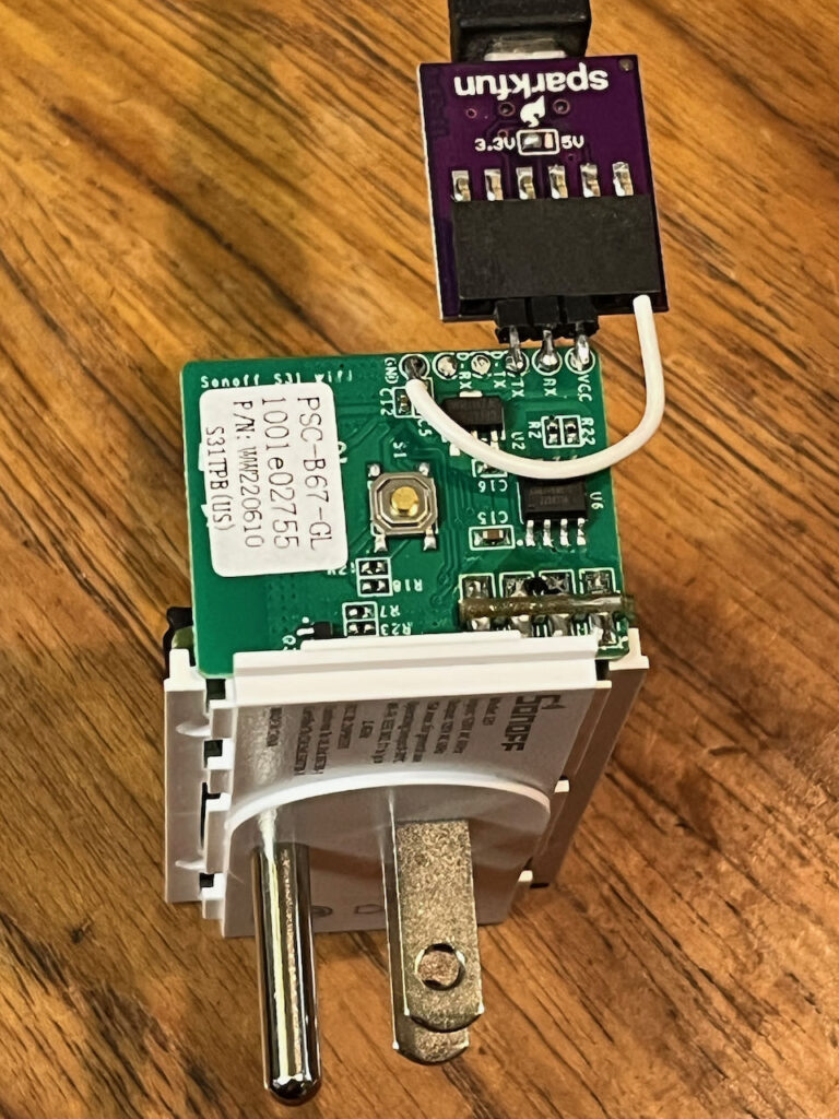
I temporarily soldered on pins and a wire to program my first units. A programming clip described below eliminates the need to solder at all and makes programming multiple units much easier.
How:
Here’s an overview of the process. Please review all the notes below this list before starting.
- Review overview of process and safety concerns
- Flash firmware
- Configure the module
- Analyze battery charge profile
- Modify a script for your use
- Load script
- Test functionality
Review Overview:
We will be doing the flashing differently than usual, but before we start Tasmota has a page on the S31 that is worth reviewing. It has important safety notes and links to the video below as well as other resources.
https://tasmota.github.io/docs/devices/Sonoff-S31/
The first 6 minutes of the video below do a great job of covering how to open up the unit and connect the FTDI USB to serial adaptor. Once the unit is flashed with the new code, the wires can be removed and the case reassembled before plugging it in.
Flash Firmware:
The standard Tasmota build is not capable of the functions we need and therefore my process for loading the new Tasmota firmware in the S31 is a bit different than shown in the video above.
- First you’ll need to unzip this binary file my friend Hai-Yue Han compiled. It enables the more complex programming: tasmota.bin
- Open up the S31 and solder wires connecting the USB to TTL converter to the board inside. Or use the clip setup shown below.
- Warning: Do not plug the unit into AC when the cover is off! Programming power for the device comes from the USB to TTL adaptor connection.
- Insure your computer has the proper drivers installed to run your USB TTL converter.
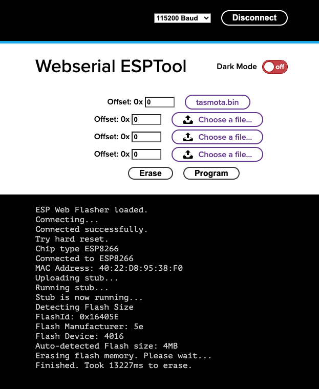
- Unlike what the video shows, go to https://jason2866.github.io/WebSerial_ESPTool/ It’s important to press and hold the reset button as you plug in the USB. Hold the button until after it has connected indicated by the GUI changing to allow for file upload.
- Erase the chip
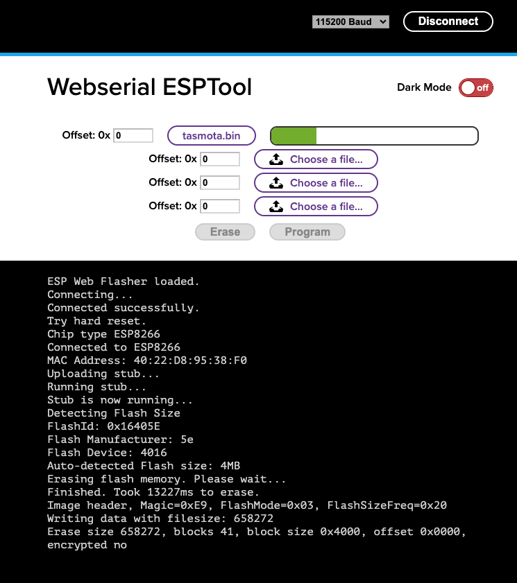
- Flash the unzipped tasmota.bin with offset of 0x0 and baud rate of 115200.
- After programming the GUI should say: “To run the new firmware, please reset your device.”
- Reset the S31 by cycling power on the USB. Or, go ahead and remove the TTL adaptor, reassemble the protective cover and plug it into 120V.
Optional Programming Clip:
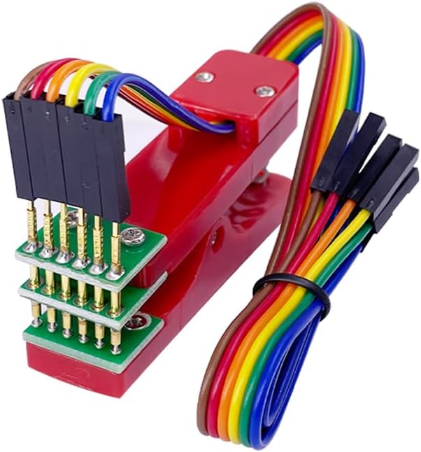
A friend shared this programming clip available from Amazon. It’s a simple solution for avoiding soldering and desoldering the USB to TTL converter to each part. You will still need one of the converters listed in the first section of this blog.
Before I knew about the above part, I made mine as shown below:
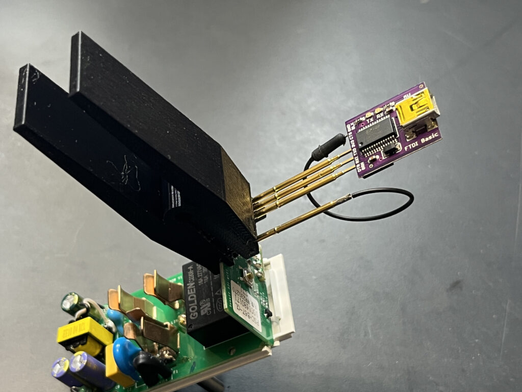
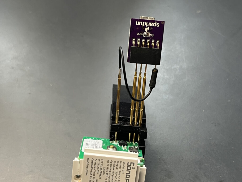
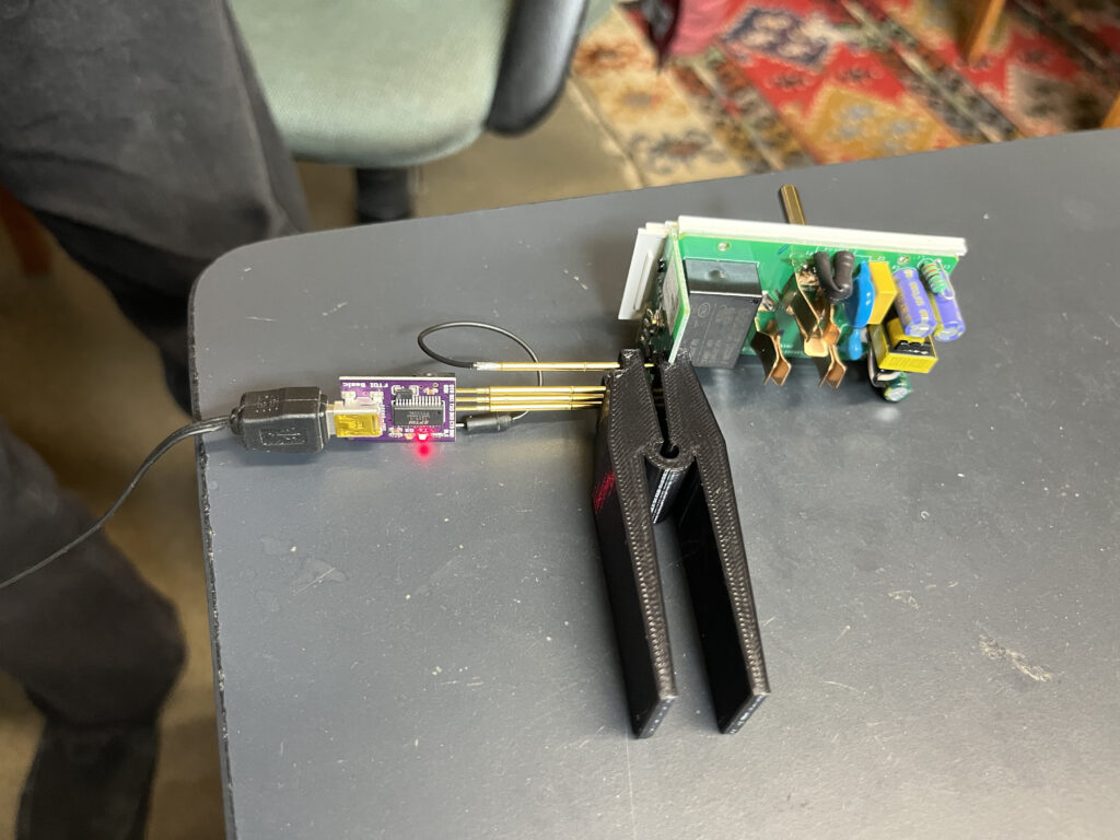
This 3D printable tool plus some pogo pins is handy for programming a bunch of them. It has very small pogo pin holes that I drilled out with a #55 drill in order to use larger 1.5mm pogo pins. You’ll have to print your own clip or like me find someone to print one for you.
Pogo-pin-programming-clip file on thingiverse.
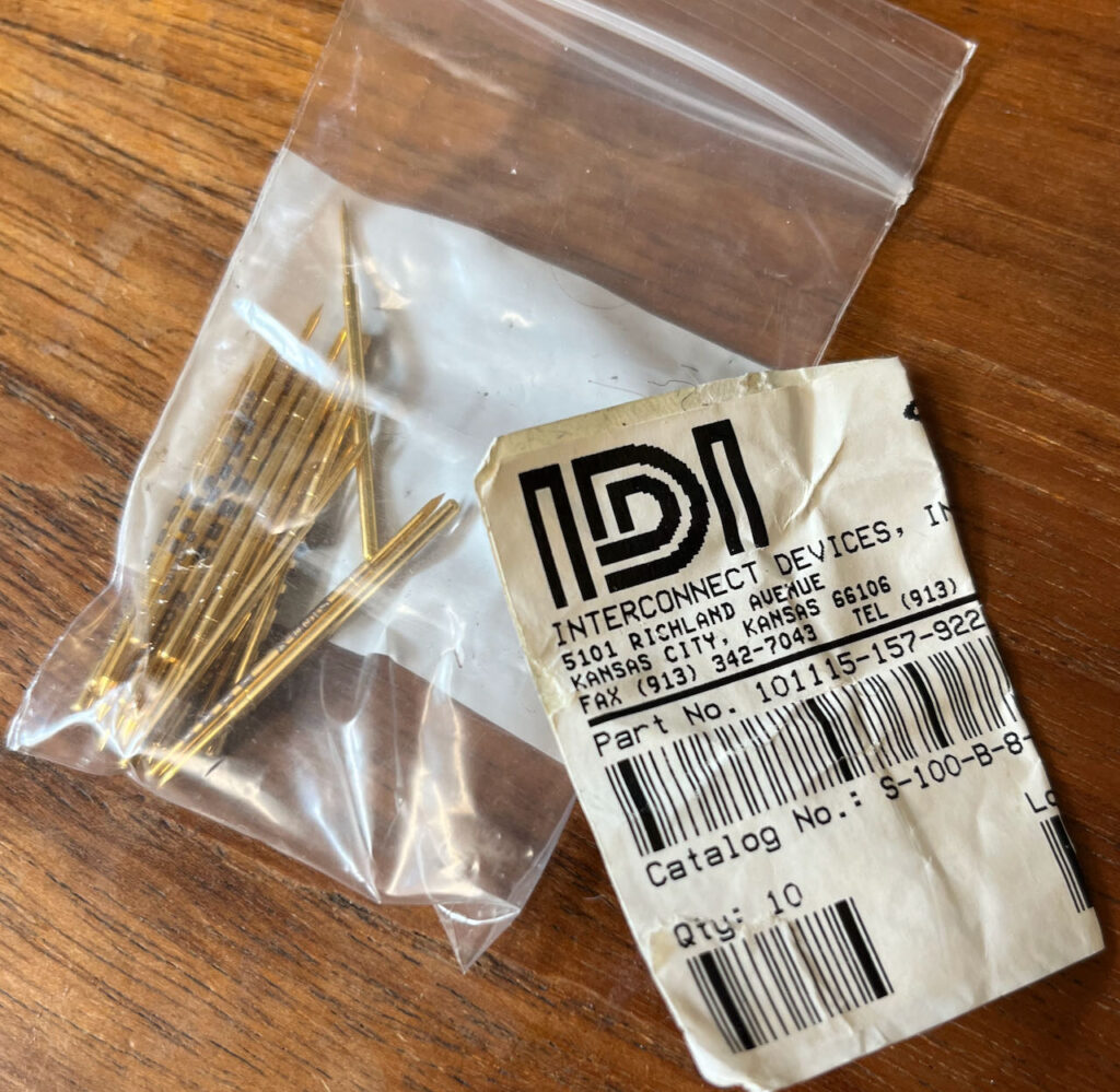
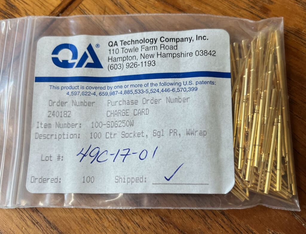
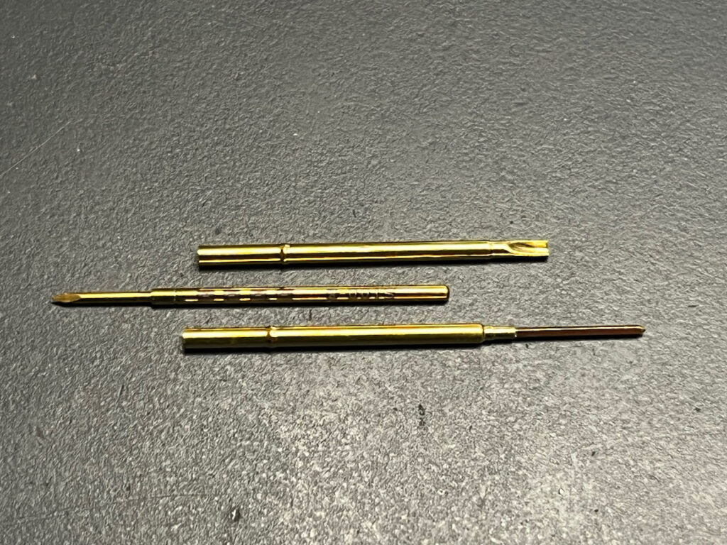
I had pogo pins and sleeves left over from long ago, these may not be easily available parts. The four contact probes are a “headless spear” PN S-100-B-8-G which allows them to be tightly pressed into the plastic after it has been drilled with a #55 drill bit (0.052″ diameter.) The short space available on this clip design doesn’t allow for pressing in the sockets, so I slide them over the end of the probes after they are in the plastic. I used three square pin sockets PN SDG250W, and a solder cup socket for the ground wire (no PN available.)
If your USB to TTL converter has a similar pinout to mine, like this SparkFun Beefy 3, then you can slide it directly onto the three square pin sockets and only have to add a ground wire, as shown in the pictures above.
Configure the module:
- Power up the S31 without holding reset button. Log into a Wifi access point named Tasmota. Eventually an automatic “login” page (captive portal) pops up for wifi configuration. The captive portal that pops up on the iPhone has a bug in that it won’t let me paste into the password field, expecting me to try to type in my complex wifi password I guess. If your password is complex it may be better to perform configuration on a desktop machine.
Select your local WiFi Network, enter the password and watch for and remember the IP address that it shows before the page vanishes. - Switch your computer WiFi back to your own local access point.
- Navigate to the noted IP address in a browser and navigate into the configuration menu.
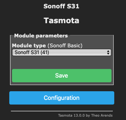
- Configure Module in the Configuration menu to a S31 and save, device will restart.
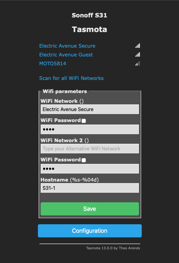
- I like to configure the WiFi by adding a Hostname of S31-1, S31-2 etc so I don’t have to remember the IP address. I found that underscores didn’t work properly, so don’t do S31_1. The ability for hostnames to work may depend on your local router configuration. Configuring routers is beyond the scope of this document.
Analyze charge profile:
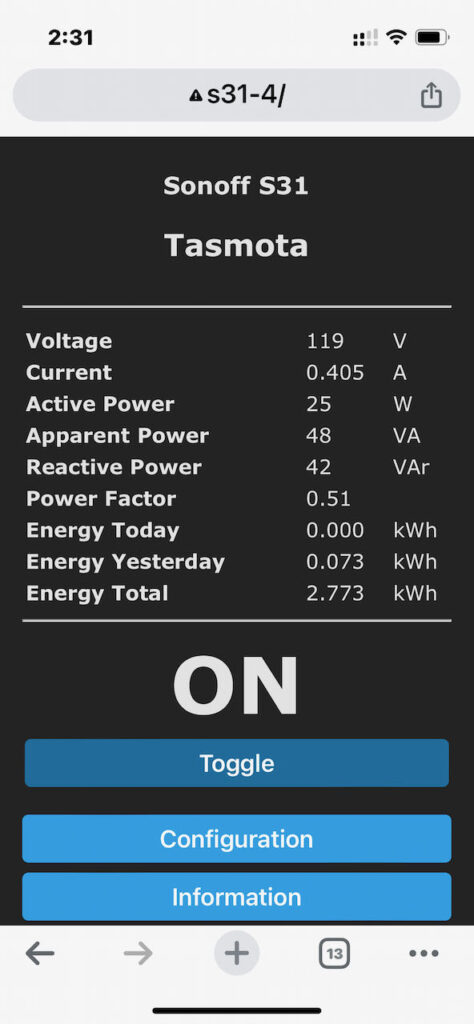
- At this time you should be able to manually control the output switch and view the power parameters as in the image below.
- Plug in the device that you want to make a profile for.
- I find it helpful to make a screen video recording of a full charge cycle using my target battery and charger so I can go back and review the charge session quickly figuring out what power levels coincide to a 80% to 90% state of charge. Subtracting the starting from ending values for ‘Energy Total’ gives the battery capacity minus losses. Finding a time in the screen recording that’s 80% of that value is a good place to look for trends in power draw changing. Some chargers with constant current outputs will slowly increase the AC power draw as the battery voltage increases, while others may run at constant power until almost full and then taper off. An important point when using the scripts below is to see if the power is rising or falling, and what numerical power level represents a good cutoff point.
- On my Bauer 20V power tool batteries the “Fast” charger power jumped around a lot, making it difficult to make an algorithm to fit. Fortunately the “Rapid” (Slow) and “Dual Port” (Fastest) chargers behaved better.
Modify the script:
- Tasmota has a scripting language called Rules. Rules don’t seem to allow comments, so I’ll show an example script for an Ebike below with translations:
- Ebike rule:
Rule1
ON system#boot DO var1 0 ENDON
ON ENERGY#Current==0.0 DO if (var1!=0) RuleTimer1 0; var1 0 endif BREAK
ON ENERGY#Current>=1.4 DO if (var1!=0) RuleTimer1 0; var1 0 endif BREAK
ON ENERGY#Current<1.4 DO if (var1!=1) RuleTimer1 30; var1 1 endif ENDON
ON Rules#Timer=1 DO Power1 OFF ENDON - This script turns off the outlet when current is not 0 and continuously under 1.4 Amps for 30 seconds. It uses the variable var1 and RuleTimer1. My comments for each line follow:
Reset at boot var1 to 0. 1 indicates the timer is in countdown mode
if current is 0, it clears the countdown and resets timer to 0, don’t continue
if current is over 1.4, it clears the countdown and resets timer to 0, don’t continue
If current below 1.4 and countdown has not started, start countdown and set timer to 30
If timer drops to 1, turn off outlet. - The script can easily be changed to trigger on higher than a value instead of lower than by swapping the < > symbols in lines 3 and 4.
- I’m now using ENERGY#Power as a determining variable instead of ENERGY#Current since I figure it won’t change so much when the line voltage changes.
- The adjustability of this method is pretty coarse on some devices, but it seems to be relatively repeatable, though I’d be sure to recheck function when using a script on a new device that may have different calibration.
- I will post more sample scripts (Rules) further below.
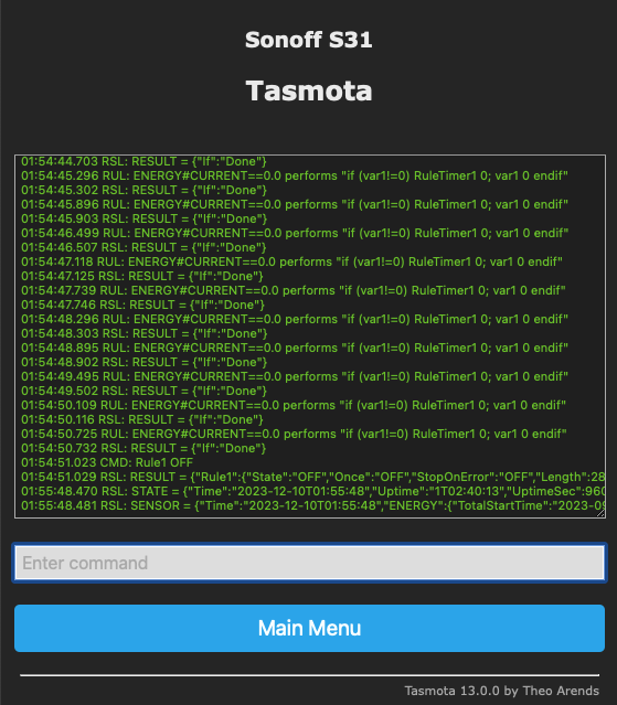
Example of the Console window, near the bottom I sent the command to turn off Rule1
Load script:
- Rules are loaded, turned on and monitored in the Console. I’m only using Rule1 of three available ones.
- In order to load a Rule it is only necessary to paste the rule into the console command area starting with Rule1… it’s ok to paste in a Rule with line feeds. Use the return key to enter the command or Rule.
- Pasting in a new Rule1 overwrites the old one.
- Once Rule1 is entered, it should be turned on with the command: Rule1 ON
- Rules can be disabled with the command: Rule1 OFF
- Once a Rule is loaded and running, the console will show lines being run about every 3 seconds.
- Rules and settings stay in memory through power cycles. Once you have a working system there is no need to connect to the unit to WiFi unless you want to monitor or change something.
- Usage is as simple as pushing the button on the side to turn on the output and the Rule will turn it off when conditions are met.
Test functionality:
- Once you have a Rule running, all that’s left is to insure that it is doing what you want.
- On laptops, or devices with state of charge displays it’s easy to see how full they got before shutting off.
- For other devices like power tool batteries I measure the terminal voltage and divide it by the number of cells to estimate how full they are. Generally I like to see 3.8V to a maximum of 4V per cell. Some batteries need to be in the tool to turn on and allow a Voltage reading and for those I go by the Watt Hours charged since empty.
- Caution: Watching batteries charge is a very tedious thing!
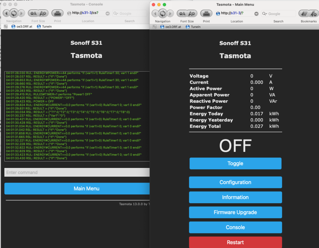
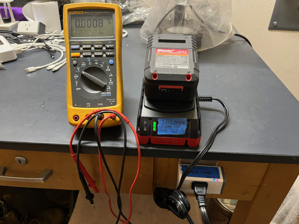
The above screen shot shows the console just after the device shut off the Bauer 20V battery charger for being at or over 44 Watts for 30 seconds.
Sample Rules:
Here are my notes followed by the rules that can be used as-is or serve as examples for further modification or testing.
—————————————————
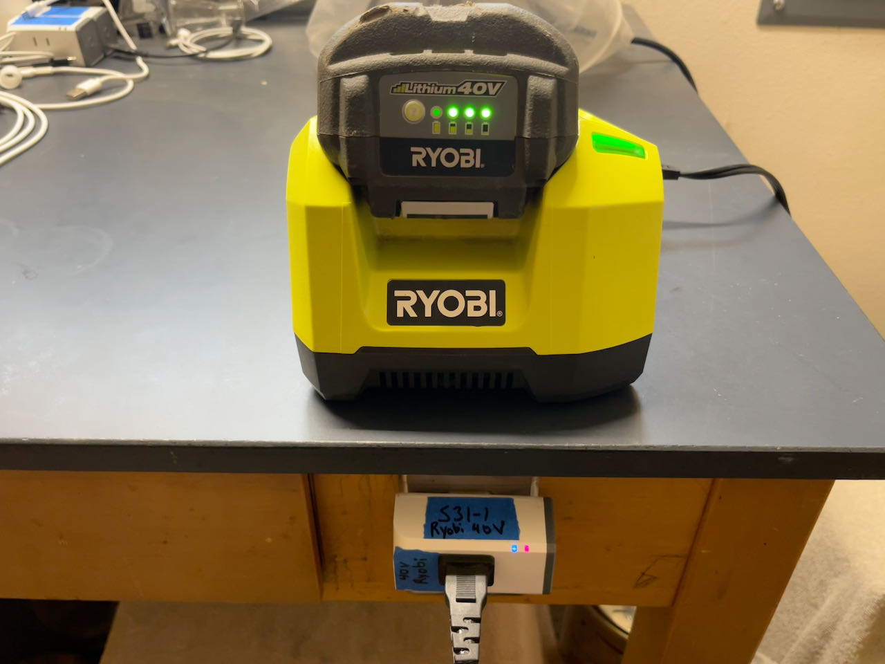
Ryobi 40V rule: For http://s31-1/
Current<0.800 charged almost to full. Taper is right at the last few wH. Want to try cutting off when over 84W since Wattage climbs as voltage rises. Once full, with SOC lights off and green light solid, charger seems to be equalizing cells, toggling between about 5W and 30W (dropping over time) with reducing duty cycle. Over 84W cutoff seemed to cut it off too early. Recorded video of full charge (Only used 83 Wh) and 90% seems to be when Power is at 60W or below. Wait until Watts drops to below 61W for 30 seconds to shut off. The following code seems to be shutting off correctly.
Rule1
ON system#boot DO var1 0 ENDON ON ENERGY#Current==0.0 DO if (var1!=0) RuleTimer1 0; var1 0 endif BREAK
ON ENERGY#Power>=61 DO if (var1!=0) RuleTimer1 0; var1 0 endif BREAK
ON ENERGY#Power<61 DO if (var1!=1) RuleTimer1 30; var1 1 endif ENDON
ON Rules#Timer=1 DO Power1 OFF ENDON
—————————————————
Bauer 20V Rule, use on black topped Rapid Charger.
Fast charger current draw is too variable to be easy.
Charge on slower “rapid” charger and record. 10/10/23
Starts at 36W, climbs as charge progresses, wattage is smooth.
108 Wh AC charge in
80% would be 86 Wh,
Limit should be set to stop at or above 45 watts for 30 seconds.
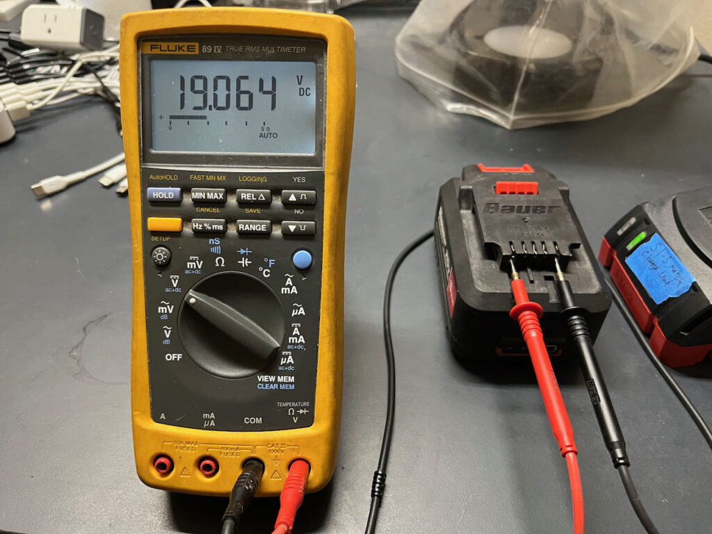
Voltage after charge to 45W limit is 20.298 average 4.06V per cell.
Voltage after charge to 44W limit is 19.8V average 3.96V per cell.
Rule1
ON system#boot DO var1 0 ENDON
ON ENERGY#Current==0.0 DO if (var1!=0) RuleTimer1 0; var1 0 endif BREAK
ON ENERGY#Power<44 DO if (var1!=0) RuleTimer1 0; var1 0 endif BREAK
ON ENERGY#Power>=44 DO if (var1!=1) RuleTimer1 30; var1 1 endif ENDON
ON Rules#Timer=1 DO Power1 OFF ENDON
—————————————————
Bauer 20V Dual Fast Charger, 4A each
Plan to only limit charge when one is charging, and keep running if 2 batteries are in.
1W standby. .2 pf
84-86W starting with new shipped battery.
133W .65pf two batteries (one cold that draws 50W on its own)
Wattage rises as it charges to 93, after which it rapidly tapers off with 9Wh left to charge, so when it hits 90W that seems like a good shut off, but if it’s over 95W keep charging since that would be 2 batteries.
The second line in this Rule uses ENERGY#Power<3 to indicate no battery present since the idle consumption of this charger is high.
Rule1
ON system#boot DO var1 0 ENDON
ON ENERGY#Power<3 DO if (var1!=0) RuleTimer1 0; var1 0 endif BREAK
ON ENERGY#Power>100 DO if (var1!=0) RuleTimer1 0; var1 0 endif BREAK
ON ENERGY#Power<90 DO if (var1!=0) RuleTimer1 0; var1 0 endif BREAK
ON ENERGY#Power>=90 DO if (var1!=1) RuleTimer1 30; var1 1 endif ENDON
ON Rules#Timer=1 DO Power1 OFF ENDON
—————————————————
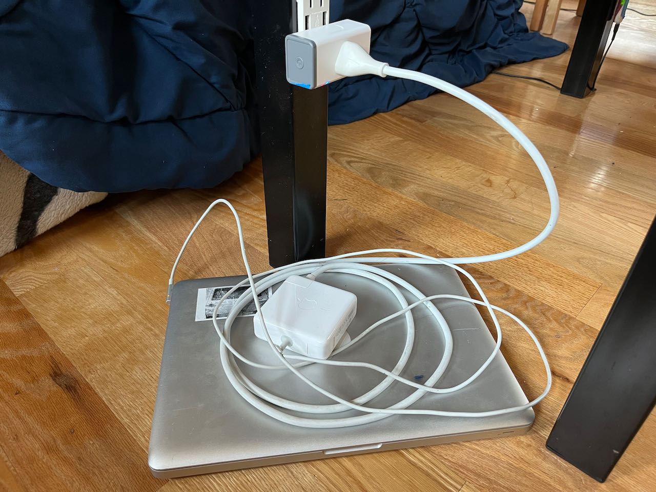
Macbook Pro, this rule only works for charging when sleeping. During use it will not limit charge level.
At 78% SOC power dropped to 22W, goes higher and stays there a while when woken up.
Drops to 21W and then rapidly drops at about 90%, try that cutoff.
Tested at 65% SOC, Charged to 78% and turned off. Seems close enough for me.
22W gave 75%, Lets try 21W.
21W gave a perfect 89% SOC starting in the 60’s. Looks good.
Rule1
ON system#boot DO var1 0 ENDON
ON ENERGY#Current==0.0 DO if (var1!=0) RuleTimer1 0; var1 0 endif BREAK
ON ENERGY#Power>21 DO if (var1!=0) RuleTimer1 0; var1 0 endif BREAK
ON ENERGY#Power<=21 DO if (var1!=1) RuleTimer1 30; var1 1 endif ENDON
ON Rules#Timer=1 DO Power1 OFF ENDON
END:
Thanks for reading, I hope you find fun in this project.
Please comment with issues/corrections that you notice and let me know if it worked for you.
-Otmar
Last edited and updated on 11/16/2024
This site contains paid links, by buying through these links I may receive a commission for the sale. This has no effect on the price for you.
Thanks for this post – it helped me a lot!